-260719-4-edited.png)
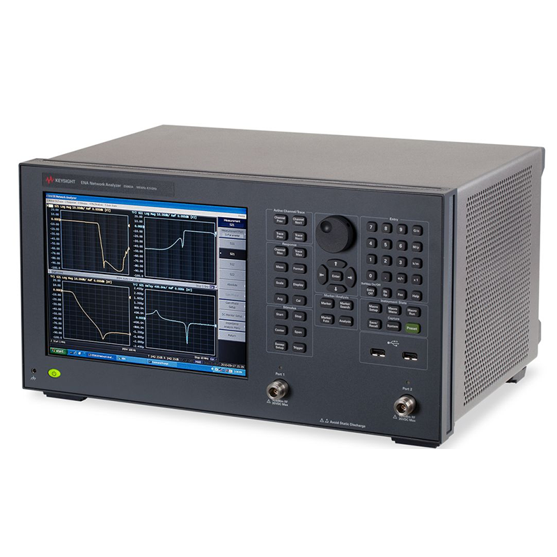
How Network Analyzers Work?
Network analyzers are the most commonly used instruments in RF testing, capable of measuring various electrical and RF parameters such as transmission, reflection, and phase. They are indispensable in nearly all RF and microwave product testing. Network analyzers are categorized into vector network analyzers and scalar network analyzers, with the primary distinction being that vector network analyzers can measure phase information. Vector network analyzers are also the most commonly used type.
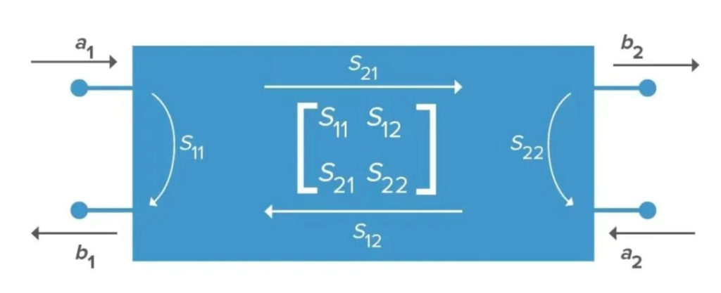
The most common function of a network analyzer is measuring S-parameters. S-parameters, also known as scattering parameters, describe the frequency-domain characteristics of a transmission channel. They are network parameters based on the relationship between incident and reflected waves, making them suitable for microwave circuit analysis. The S-parameters of a two-port device are defined as shown in the figure below.
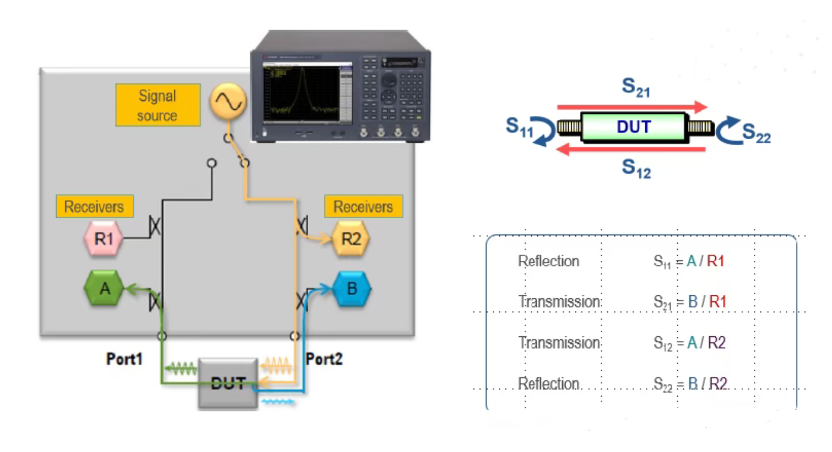
The internal structure of a network analyzer is shown in the figure below. Each port contains two receivers that detect signals via directional couplers. One receiver monitors the output signal, while the other monitors signals entering the instrument through that port, such as reflected signals or signals transmitted from other ports.
This configuration enables S-parameter testing. Taking two-port S-parameters as an example:
When transmitting a signal from one port, the ratio of the reflected signal received by that port’s receiver to the transmitted signal yields S11. The ratio of the transmitted signal received by the second port’s receiver to the signal transmitted from the first port yields S21.
When transmitting from the second port, the S22 parameter is obtained by comparing the reflected signal received at the second port with the transmitted signal. The S12 parameter is obtained by comparing the transmitted signal received at the first port with the signal transmitted from the second port.This process yields the S-parameters for a two-port device.
In addition to S-parameters, network analyzers are commonly used for time-domain testing. They can measure the propagation delay of devices and utilize the TDR function to detect impedance discontinuities. When using surface acoustic wave (SAW) filters, it is typically necessary to measure their propagation delay.
SAW filters convert electrical signals into acoustic signals for filtering before converting them back to electrical signals for output. Due to the relatively slow speed of sound, most SAW filters exhibit significant transmission delays. The figure below shows a typical time-domain test curve for a SAW filter, with the horizontal axis representing time and the vertical axis representing loss.
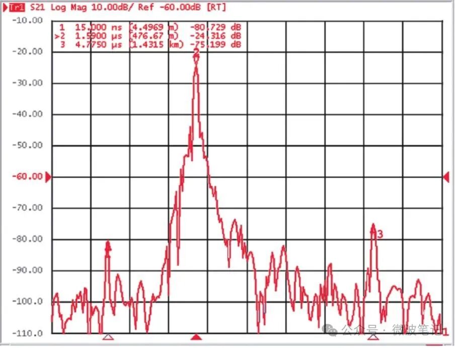
The point with the lowest loss, marked as maker2, corresponds to the horizontal coordinate representing the transmission delay of the acoustic filter. This minimum loss value indicates the filter’s transmission loss. The point on the left, marked as maker1, represents the electrical signal leakage from the filter’s input to its output. Since this signal is not converted into an acoustic signal, its delay is extremely short, on the order of nanoseconds.
The point on the right, marked as maker3, represents the third round-trip of the acoustic signal. This occurs when the acoustic signal travels from the input to the output, reflects back to the input, and then reflects again to the output. Since the acoustic signal traverses the filter three times, its delay is essentially three times the transmission delay.
What should be considered when customizing batteries for network analyzers?
Network analyzers are typically laboratory or professional equipment, usually powered by external power supplies and rarely equipped with built-in batteries. When designing battery-powered portable network analyzers, the following key factors must be comprehensively considered:
1. Energy Requirements and Runtime
· Calculate battery capacity based on the network analyzer’s power consumption (e.g., power requirements of signal sources, receivers, processors, etc.) to ensure it meets the expected operating time. For example, if the device consumes 10W and needs to operate continuously for 8 hours, the battery capacity must be at least 80Wh.
· Account for power consumption variations across different operating modes (e.g., scanning frequency, resolution bandwidth) by implementing dynamic power management strategies to minimize energy usage during standby or low-power modes.
2. Battery Type Selection
· Ternary Lithium-Ion Battery: High energy density, low self-discharge rate, and long cycle life make it the preferred choice for portable devices. Select appropriate battery specifications (e.g., Tefoo’s 18650 lithium-ion battery) based on device size and weight constraints.
· Safety: Lithium-ion batteries carry risks such as overcharging, over-discharging, and overheating. Comprehensive protection circuits must be designed, incorporating functions like overcurrent protection, overvoltage protection, and temperature monitoring.
3. Intelligent Power Management System
· Charging Management: Designed with efficient charging circuits supporting fast charging and trickle charging to extend battery life. Must be compatible with multiple charging interfaces.
· Battery Monitoring: Utilizes the Battery Management System (BMS) to monitor battery capacity, voltage, temperature, and other parameters in real time, providing accurate power display and low-battery warning functions.
· Power Switching: Enables seamless switching between external power sources and the battery, ensuring the device continues to function normally during charging.
4. Electromagnetic Compatibility (EMC)
· Battery circuits may generate electromagnetic interference that affects the measurement accuracy of network analyzers. Shielding, filtering, and other measures should be employed to minimize interference from battery circuits to RF signals.
· Select low-noise battery management system chips and power circuits to prevent coupling with high-frequency signals.
5. Thermal Management Design
· Batteries generate heat during charging and discharging, and elevated temperatures may compromise battery lifespan and performance. Design appropriate thermal structures, such as heat sinks and ventilation holes, to ensure batteries operate within safe temperature limits.
· Monitor battery temperature and automatically reduce device power or suspend operation when temperatures become excessively high.
6. Safety and Reliability
· Batteries must comply with relevant safety standards (e.g., UN38.3, IEC 62133) to ensure safety during transportation and use.
· Incorporate redundant protection mechanisms, such as short-circuit protection and overheat protection, to prevent safety incidents caused by battery failures.
Conclusion
In summary, network analyzer battery design requires a comprehensive balance of energy supply, safety, and electromagnetic compatibility to ensure device performance and reliability. TEFOO’s smart lithium-ion battery packs perfectly meet the demands of network analyzers. For purchasing or customizing network analyzer batteries, please contact TEFOO’s professional technical team.