
By TEFOO Battery Engineering Team | Medical Power Systems Division
1. Introduction
Syringe pumps and infusion pumps are among the most safety-critical portable medical devices in clinical use today. Whether delivering vasopressors in an ICU, titrating anesthesia during surgery, or administering chemotherapy on an oncology ward, these devices must maintain uninterrupted, accurate fluid delivery for hours on end. A single unexpected battery depletion event can pause a life-sustaining infusion, trigger a nursing alarm, and in the worst case compromise patient outcomes.
As a senior lithium-battery R&D engineer who has led custom pack programs for more than a dozen Class II medical-device OEMs, I can tell you that the battery pack is rarely an afterthought in a successful pump program—it is engineered in parallel with the motor drive, the drug-library firmware, and the mechanical enclosure from day one. Off-the-shelf battery packs almost never meet the combination of form factor, runtime, fuel-gauge accuracy, communication protocol, and regulatory traceability that syringe and infusion pumps demand. That is precisely why custom battery pack development has become standard practice for mid-to-high-volume pump platforms.
This guide walks through the engineering decisions that define a safe, reliable, and regulatory-ready custom battery pack for syringe and infusion pumps in 2026. We cover cell selection, BMS architecture, SMBus/I2C fuel gauging, the compliance landscape (including the new EU Battery Regulation 2023/1542), and how to evaluate a contract battery manufacturer.
2. Understanding the Power Profile of Syringe and Infusion Pumps
Before selecting any cell or BMS, you must characterize the device’s electrical load. Syringe pumps and infusion pumps share a motor-driven pumping mechanism, but their duty cycles and power envelopes differ meaningfully.
2.1 Syringe Pumps
Syringe pumps drive a linear plunger at very low flow rates—typically 0.1 mL/h to 150 mL/h for adult models. The DC gear motor operates in short, high-torque bursts: a stall-current spike during the first few milliseconds of each step, followed by a much lower holding current. Quiescent current from the MCU, display, and alarm speaker is continuous. Typical pack configurations in the field range from 2S1P (7.4 V nominal, 2,000–2,600 mAh) to 3S1P (11.1 V nominal, 2,600–5,200 mAh), delivering 4–8 hours of continuous operation at 5 mL/h.
2.2 Infusion (Volumetric) Pumps
Volumetric infusion pumps use peristaltic or roller-clip mechanisms to deliver larger volumes (up to several L/h). Their motors run longer and draw more average current, and multi-channel stations may power two to four pumping modules from a single removable battery. Packs commonly land at 3S1P or 4S1P (14.8 V nominal), 3,000–5,000 mAh, with required runtimes of 6–12 hours on battery.
2.3 Key Electrical Design Targets
| Parameter | Syringe Pump (Typical) | Infusion Pump (Typical) | Engineering Note |
| Nominal voltage | 7.4 V – 11.1 V | 11.1 V – 14.8 V | Matches motor driver and charger IC input range |
| Capacity range | 2,000 – 5,200 mAh | 3,000 – 6,000 mAh | Driven by required runtime at max flow rate |
| Peak current draw | 2–4 A (motor stall) | 3–6 A (multi-channel) | BMS FET and cell rating must cover 2× stall |
| Continuous current | 0.3–0.8 A | 0.8–2.0 A | Sets cell continuous-discharge rating |
| Operating temperature | +5°C to +40°C | +5°C to +40°C | Cell derating required below +10°C |
| Required runtime | ≥ 4 h (at 5 mL/h) | ≥ 6 h (continuous) | Verify at worst-case flow + full display backlight |
| Fuel-gauge accuracy | ±3% SOC (target ±1%) | ±3% SOC (target ±1%) | Prevents unexpected low-battery shutdown |
Table 1. Representative power-profile targets for syringe and infusion pump battery packs (2026 field data).
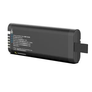
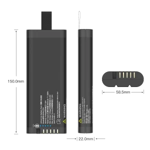
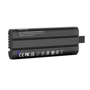
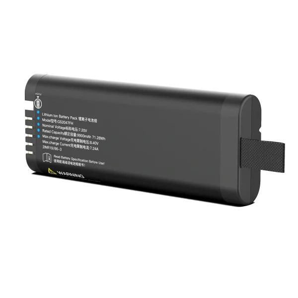
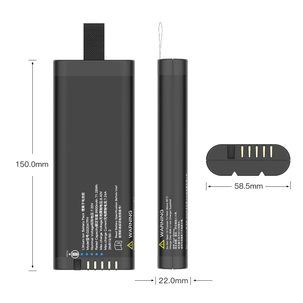
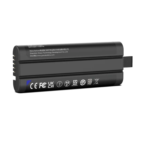
GS2047FH
7.2V/10350mAh/71.28Wh
3. Core Design Decisions for a Custom Medical Battery Pack
3.1 Cell Chemistry and Form Factor
NMC (nickel-manganese-cobalt) cylindrical 18650 cells—typically 2,500–3,500 mAh—dominate this application space for good reason: proven safety track record, high energy density, mature supply chain, and predictable cycle life. Medical-grade pouch cells are chosen only when the pack height envelope cannot accommodate an 18650 (e.g., handheld ultra-compact syringe drivers).
We strongly specify cells from tier-1 manufacturers with full ISO 13485-compatible PPAP documentation, because the cell is the single component you cannot redesign after production freeze. Cherry-picking sorted cells with matched capacity (±20 mAh) and internal resistance (±5 mΩ) is a low-cost step that materially improves pack cycle life and fuel-gauge linearity.
3.2 BMS Architecture: Dual-Level Protection Is Non-Negotiable
Medical battery packs cannot rely on a single protection IC. The BMS architecture I specify for pump programs includes:
- Primary protection: A primary analog front-end (AFE) IC that handles overvoltage, undervoltage, overcurrent, short-circuit, and cell-balance thresholds during normal operation.
- Secondary hardware protection: A secondary, independent thermal fuse (TCO) or secondary protector IC that physically interrupts the discharge path if the primary FET fails short or pack temperature exceeds the hard threshold (typically +70°C).
- Fuel gauge: A precision fuel-gauge—usually a TI bq series or Renesas/RAA coulomb-counter device—that reports SOC to within ±1–3% even under the pump’s pulsed motor load.
- Fault isolation: An E-fuse or resettable fuse on the discharge output for additional short-circuit margin, plus NTC thermistors for pack-temperature monitoring sent to both the BMS and the pump host.
3.3 SMBus / I2C Communication
Modern pumps do not merely read pack voltage over an analog line—they negotiate with the battery over SMBus (System Management Bus, SMBus 3.0 compatible) or I2C. The host reads State of Charge (SOC), State of Health (SOH), cell voltage, pack temperature, cycle count, manufacturer name, and serial number in real time. This enables three clinical capabilities that regulatory reviewers expect:
- Accurate remaining-infusion-time estimates displayed on the pump UI.
- Predictive maintenance alerts when pack SOH drops below 80% of rated capacity.
- Battery-authentication to prevent counterfeit third-party packs from being used in clinical settings.
For OEMs that need richer diagnostic data (e.g., asset-tracking hospitals), CAN bus support is available on higher-tier BMS designs, though SMBus remains the de facto standard for portable pumps.
3.4 Mechanical and Thermal Design
A removable pump battery must survive a 1.0 m drop onto concrete (per IEC 60601-1Clause 15.3), IP54 or better ingress protection against fluid spills, and a minimum 5,000-cycle insertion/removal life. The pack enclosure uses UL94 V-0 flame-retardant PC/ABS, with a welded or heat-shrunk inner cell wrap. Thermal path design keeps cell surface temperature within +5°C of ambient even during fast-charge at 1 C—critical because elevated cell temperature is the dominant driver of calendar aging and the hardest safety failure mode in lithium-ion systems.
3.5 Charging Strategy
Most pumps charge the pack while docked, at 0.5 C–0.8 C. The charge profile must be CC-CV (constant current to 4.20 V/cell, then constant voltage until charge current tapers to C/10), with charge suspend thresholds above +40°C and below +10°C. I strongly recommend specifying charge-voltage accuracy of ±20 mV per cell—looser tolerance directly shortens cycle life and raises safety risk.
4. The 2026 Regulatory Compliance Landscape
A custom medical battery pack is not a commodity component—it is a subsystem of a Class II medical device and is regulated as such. Below is the standards checklist our engineering team runs for every pump program.
| Standard / Regulation | Scope | Why It Matters for Pump Packs |
| IEC 60601-1 (3.2 ed.) | General safety & essential performance of medical electrical equipment | Governs leakage current, mechanical safety, and EMC integration of the pack inside the pump |
| IEC 60601-2-24 / GB 9706.27 | Particular requirements for syringe pumps and perfusion controllers | The dedicated pump-particular standard; references pack runtime and alarm behavior |
| IEC 62133-2:2017+A1:2021 | Safety requirements for portable sealed secondary lithium cells/batteries | Cell and pack-level safety certification required by FDA, EU, and most notified bodies |
| ISO 13485:2016 | Medical device quality management system | Battery manufacturer must operate under a QMS traceable to the pump OEM’s device file |
| UN38.3 | Transport safety of lithium batteries | Mandatory for shipping packs by air, sea, or road; includes altitude, thermal, vibration, and short-circuit tests |
| CE marking / UKCA | EU and UK market access | Self-declaration to EMC + LVD + RED as applicable; packs integrated into the pump’s DoC |
| IEC 61000-4 / CISPR 11 | EMC emissions and immunity | The pack’s switching charger and SMBus lines must not disrupt pump alarms or nearby telemetry |
| EU Battery Regulation 2023/1542 | EU-wide battery sustainability, labeling, and carbon-footprint rules | Applies from 2025–2027; requires digital battery passport, recycled-content claims, and removability/replaceability for portable batteries |
| IEC 60529 IP54 / IPX1 | Ingress protection | Pump packs routinely target IP54 against fluid spillage in clinical environments |
Table 2. Standards and regulatory framework for syringe/infusion pump battery packs (as of 2026).
Note on EU 2023/1542: because medical-device batteries fall under the scope of this regulation, OEMs should work with a pack supplier who can provide material-compliance declarations, recycled-content documentation, and support for the forthcoming digital battery passport. The removability-and-replaceability provisions are particularly relevant to pump packs, which are routinely swapped between charged and depleted units in hospital settings.
5. Evaluating a Custom Battery Pack Manufacturer
Choosing a contract pack manufacturer is one of the highest-leverage decisions in your program. The wrong supplier will hand over a nominally compliant pack that fails on fuel-gauge accuracy, field reliability, or audit readiness. Based on programs I have reviewed, the following comparison reflects what I ask during supplier qualification.
| Criterion | Generic Consumer Pack Supplier | Medical-Grade Custom Pack Supplier (e.g., TEFOO) |
| Quality system | ISO 9001 only | ISO 13485:2016 certified, with device-history-record (DHR) support |
| BMS capability | Basic over/under-voltage protection only | Dual-level protection, SMBus/I2C fuel gauge, coulomb counting, SOH reporting |
| Cell traceability | Batch-level, mixed-brand allowed | Full cell lot traceability, tier-1 NMC cells, PPAP documentation |
| Regulatory support | UN38.3 test summary | IEC 62133-2 test report, ISO 13485 audit support, design-history-file (DHF) collaboration, EU 2023/1542 documentation |
| Customization | Standard enclosure sizes | Custom shape, connectors, communication protocol, mechanical interface |
| Cycle life warranty | ≈ 300–500 cycles to 70% | ≥ 500–1,000 cycles to 80% at 0.5 C/0.5 C, +25°C |
| NRE / MOQ model | High tooling NRE, large MOQ | Moderate NRE, flexible MOQ for pilot and production ramp |
| Field reliability data | Limited | Reference deployments in syringe/infusion pump programs with documented field-failure rates |
Table 3. Supplier qualification criteria for medical pump battery packs.
At TEFOO, our medical battery program is built specifically around this profile: ISO 13485-certified production lines, SMBus 3.0 fuel-gauge packs in 2S–5S configurations, full UN38.3 and IEC 62133-2 certification, and an engineering team that collaborates with pump OEMs from the architecture phase through design-history-file closure. We treat the battery pack as a co-developed subsystem, not a sourced commodity—because in a clinical setting, that is exactly what it is.
6. Frequently Asked Questions
6.1 Why not just use an off-the-shelf laptop power-bank battery?
Consumer battery packs lack dual-level hardware protection, precision fuel gauging, SMBus authentication, and ISO 13485 traceability. They also carry no medical-device regulatory documentation, which means your pump would fail technical-file review and your clinical risk file would be incomplete.
6.2 What pack voltage should we design for—7.4 V or 11.1 V?
It depends on your motor driver and peak stall current. Most syringe pumps settle at 2S1P (7.4 V) or 3S1P (11.1 V); multi-channel infusion stations often move to 4S1P (14.8 V). We recommend running a motor-current budget at the earliest hardware review before locking the cell configuration.
6.3 How accurate does the fuel gauge need to be?
Target ±3% SOC under typical load, and ±1% under steady-state infusion. Pumps that display a rough percentage surprise clinicians with unexpected depletion alarms; SMBus-based coulomb-counting gauges trained on your actual motor waveform achieve this reliably.
6.4 How long should the pack last in the field?
Plan for a 5-year service life and a minimum of 500 charge–discharge cycles to 80% rated capacity. Clinicians expect packs to survive the product’s entire 7–10 year field life; designing for only 300 cycles creates a predictable after-sales problem.
6.5 Does EU 2023/1542 affect our pump battery?
Yes. Portable industrial and medical batteries are in scope. Expect recycled-content declarations, carbon-footprint documentation, and the digital battery passport to be required as delegated acts roll out through 2027. Start requesting this documentation from your pack supplier now.
6.6 Can the battery be charged while the pump is infusing?
Yes, and most hospital workflows expect it. The charger and BMS must support simultaneous charge and discharge (charge-through operation) without interrupting infusion, and the pack must not exceed temperature limits during overlap. This is a firmware and thermal-design requirement that should be specified in the development contract, not discovered later.
6.7 What is the typical development timeline for a custom pack?
From signed specification to production-ready qualification: approximately 14–20 weeks, including cell selection, EVT/DVT builds, IEC 62133-2 and UN38.3 testing, and design-history-file support. Budget an additional 4–6 weeks if the pack must be integrated into a new IEC 60601-1/2-24 technical file.
7. Conclusion
Designing a custom battery pack for syringe and infusion pumps is fundamentally a safety-and-reliability engineering exercise, not a sizing exercise. The winning pack balances runtime and weight, delivers trust-inspiring fuel-gauge accuracy, carries dual-level hardware protection, and is built under an ISO 13485 quality system that your notified body will accept without hesitation. The standards landscape in 2026—IEC 60601-1, IEC 62133-2, UN38.3, and the emerging EU Battery Regulation 2023/1542—sets a high bar, but it is a bar that any serious medical-battery partner should already be clearing.
If you are starting a new syringe or infusion pump platform, engage your battery-pack supplier at the concept phase—not after the mechanical enclosure is frozen. The packs that cause the fewest clinical surprises are the ones co-designed with the pump, cell selection and BMS firmware tuned to your motor’s actual load waveform, and the regulatory file built in lockstep with your own. That is the engineering discipline your patients, your clinicians, and your quality auditors all deserve.
About TEFOO: TEFOO is a specialist in custom smart battery packs for medical and industrial equipment, including syringe pumps, infusion pumps, patient monitors, and ventilators. Our ISO 13485-certified teams deliver SMBus-enabled, IEC 62133-2 and UN38.3-certified packs to medical-device OEMs worldwide. Contact our engineering team to discuss your next pump platform.