1. Introduction
A low-noise battery for a torque sensor is a rechargeable lithium-ion battery pack engineered to keep output voltage ripple, electromagnetic interference (EMI) and load-transient fluctuation low enough that they do not disturb the sensor’s microvolt-level bridge signal. It combines matched cells, a smart battery management system (BMS), dedicated low-noise regulation for the analog front end, controlled layout and shielding, and—where required—digital communication such as SMBus or I²C.
Torque sensors convert mechanical torque into a measurable electrical signal. In battery-powered or field-installed systems—wireless rotary torque sensors, handheld fastening tools, robotic joints, mobile test rigs and portable calibration instruments—the battery pack is the sensor’s immediate power source. An ordinary consumer-grade pack often injects ripple and switching noise that appear as reading jitter, zero drift or a degraded signal-to-noise ratio (SNR), even when the sensor itself is correctly calibrated.
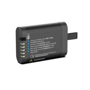
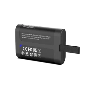
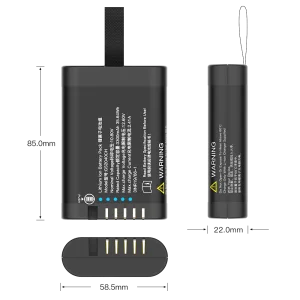
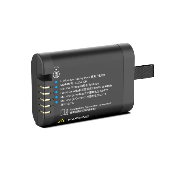
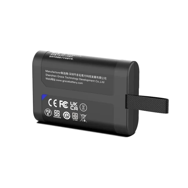
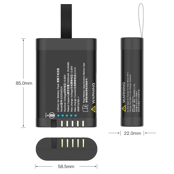
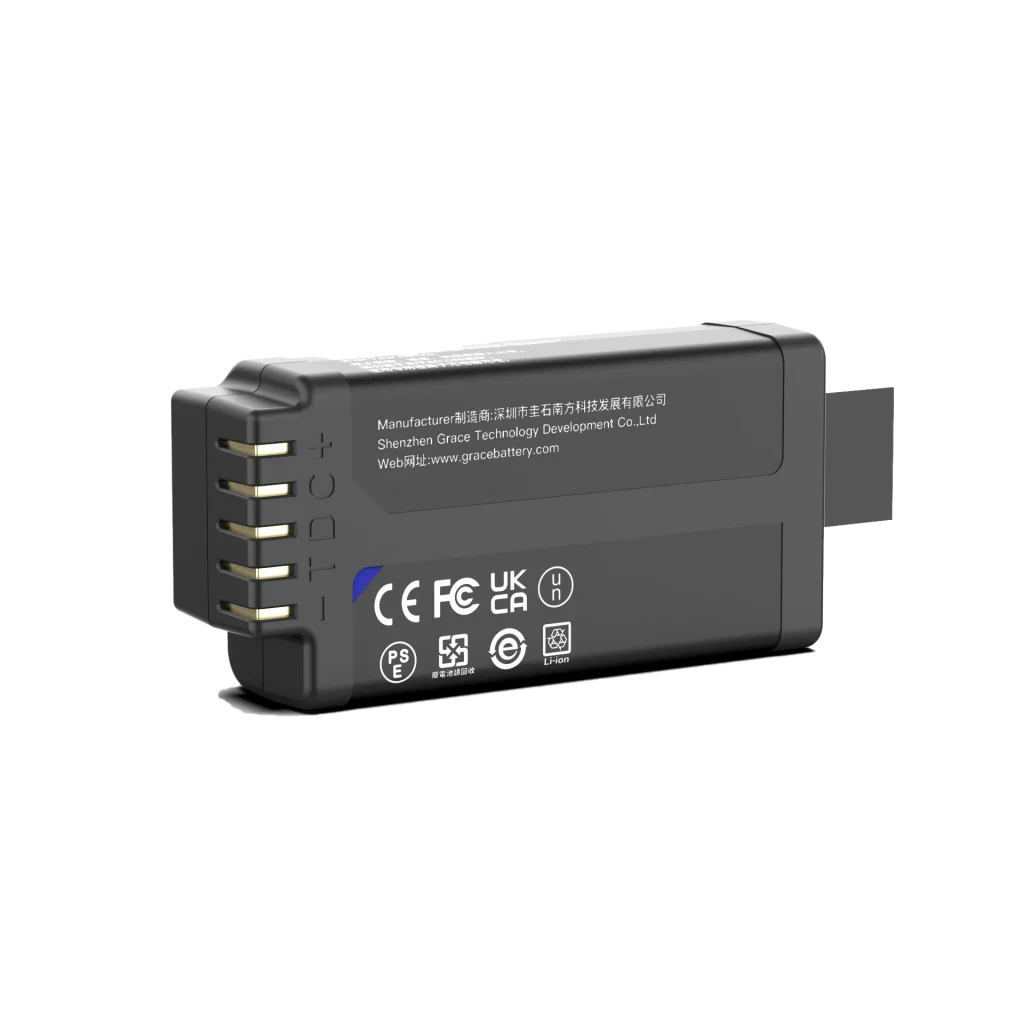
GS2040CH
10.8V/3450mAh/35.64Wh
This guide explains where battery-borne noise enters the torque measurement chain, how “low noise” should be quantified in a battery specification, how a dedicated low-noise pack is architected, how to compare suppliers and what certifications to request. It is intended for sensor OEM hardware engineers, test-bench system integrators and procurement engineers evaluating battery partners.
2. How Torque Sensors Are Powered—and Where Battery Noise Enters the Signal Chain
2.1 Typical Torque Sensor Signal Chain
Most industrial torque sensors fall into two electrical categories. Strain-gauge transducers use a Wheatstone bridge whose excitation is commonly 5–10 VDC (many designs use 10 VDC), and whose raw bridge output is typically in the 2–10 mV/V range. Sensors with a built-in amplifier or transmitter are powered at 12 VDC (for example 12 V ±0.5 V) or 24 VDC (often a 12–32 VDC range), and output an analog voltage (0–5 V, 0–10 V), current loop (4–20 mA), or digital fieldbus signal such as CAN or RS-485.
The complete power and measurement chain runs as follows: battery pack → protection and BMS → regulation → sensor excitation and analog front end → Wheatstone bridge → instrumentation amplifier → ADC or signal conditioner → output interface. Noise introduced at any stage upstream of the amplifier can be amplified together with the torque signal.
2.2 Where Noise Couples In
- Supply ripple modulates bridge excitation. Bridge output is proportional to excitation voltage; any ripple on the excitation rail therefore appears directly as fluctuation in the measured torque signal.
- Conducted noise. Ripple from DC-DC converters, BMS MOSFET switching and charger noise travels through power and ground conductors into the sensor supply.
- Radiated EMI. Switching nodes, inductors and cable harnesses radiate into nearby sensor cables and amplifier traces, especially in compact enclosures.
- Ground and common-mode noise. A shared return path lets digital or BMS current create an offset voltage at the analog front end, shifting the sensor zero point.
- Load transients. Radio transmission, solenoid actuation or motor start-up draws current pulses that sag the rail and momentarily shift the reading.
2.3 Observable Symptoms on the Host Equipment
- Reading jitter or an elevated noise floor even under static load.
- Zero drift after warm-up, or offset shift when a parallel load switches on.
- SNR degradation and calibration instability; intermittent out-of-spec readings.
- Failure of conducted or radiated EMC acceptance tests on the integrated system.
3. What “Low-Noise” Means in Battery Specifications
“Low noise” is only meaningful when measured under stated conditions. When evaluating packs, require the supplier to report the measurement point (sensor rail, not pack terminals alone), bandwidth, load current and input voltage. The principal metrics are summarized below.
| Metric | Definition | What to Request from the Supplier |
| Output ripple (mVpp / µVpp) | Peak-to-peak AC component riding on the DC rail over a defined bandwidth. | Measured ripple at the sensor supply rail, stated bandwidth (e.g., 0.1 Hz–100 kHz), load and input voltage. |
| Noise spectral density | Noise power per hertz, expressed in µV/√Hz across frequency bands. | Spectral density curve or spot values at 10 Hz, 100 Hz and 1 kHz for the analog rail. |
| Power-supply rejection ratio (PSRR) | Ability of the post-regulator (e.g., low-noise LDO) to attenuate upstream ripple, in dB over frequency. | PSRR curve of the regulator feeding the analog front end, with target ripple residual after regulation. |
| Load transient response | Voltage deviation and recovery time under a defined current step. | Deviation magnitude and recovery time for the sensor’s worst-case current step. |
| Quiescent current and efficiency | No-load consumption versus conversion efficiency; affects runtime and heat. | Quiescent current profile and efficiency across the operating current range. |
| Isolation and grounding scheme | Separation of analog and digital returns, shielding and optional galvanic isolation. | Description of analog/digital rail separation, grounding topology and enclosure shielding. |
A pack marketed only as “low noise” without measured ripple, noise spectral density or test conditions should be treated as unverified.
4. Design Architecture of a Low-Noise Battery Pack for Torque Sensors
4.1 Cell Selection and Matching
Cells are chosen against the capacity and energy target, self-discharge requirement and mechanical envelope. Internal resistance and open-circuit voltage are matched within the pack so that cell-level current sharing stays balanced; mismatched impedance can worsen current noise and accelerate aging. Cylindrical, pouch or prismatic formats are selected according to the enclosure and vibration environment.
4.2 Smart BMS with Condition Monitoring
The BMS provides over-voltage, under-voltage, over-current, short-circuit and over-temperature protection, together with state-of-charge (SOC) and state-of-health (SOH) estimation. Configurable protection thresholds and digital fuel-gauge reporting—via SMBus, I²C or, where required, CAN—let the host monitor voltage, current, temperature and alarms without tapping noisy analog signals from the power rail. The BMS digital switching section is kept electrically separated from the sensitive analog supply.
4.3 Power-Path Topology
A robust low-noise architecture separates bulk power conversion from analog supply regulation: a DC-DC stage handles efficient battery-to-system conversion, followed by a dedicated low-noise LDO or post-regulator that feeds the sensor excitation and analog front end. Analog and digital rails are routed separately, with ferrite beads, π-type filters and bypass capacitors placed close to the load. The bridge and amplifier should never be fed directly from a switching node.
4.4 Layout, Grounding and Shielding
The power stage is physically separated from the analog section; inductors and switching nodes are placed away from sensor cables and amplifier traces. Returns follow a star or separated grounding scheme so that digital and BMS current does not flow through the analog ground path. A shielded enclosure and twisted-pair sensor leads further reduce radiated pickup, while thermal design keeps the pack within the sensor’s specified temperature range.
4.5 Communication, Firmware and Environmental Design
Fuel-gauge data, alarm thresholds and low-battery warnings can be customized in firmware for host integration. Mechanical design accounts for vibration and shock in rotating or mobile equipment; the operating temperature range, cycle life, humidity and dust protection are specified against the target application.
5. Typical Application Scenarios
- Motor and e-axle dynamometers and test benches: high-repeatability torque measurement close to drive electronics and power converters.
- Robotic joints and collaborative robots: compact, quiet onboard power for joint torque sensing in motion-control loops.
- Electric power steering (EPS), e-bike and e-scooter systems: safety-relevant torque assist where signal stability directly affects control feel.
- Wireless rotary torque sensors and shaft telemetry: battery-powered rotating units requiring stable excitation and low EMI to the on-board transmitter.
- Handheld torque wrenches and fastening tools: onboard battery powering measurement, display and wireless communication.
- Portable monitoring and calibration instruments: field-service equipment requiring stable analog measurement away from clean bench power.
6. Supplier Comparison: Choosing the Right Battery Route
In practice, torque-sensor projects are served by three supply routes: standard off-the-shelf Li-ion packs, general industrial low-noise packs, and custom packs engineered with a dedicated analog rail. The comparison below summarizes the decision criteria.
| Dimension | Standard Off-the-Shelf Pack | Industrial Low-Noise Pack | Custom Low-Noise Pack with Dedicated Analog Rail |
| Output noise | Unspecified; tens of mVpp typical. | Basic filtering; mV-level ripple. | µVpp-level ripple specified on the analog rail, measured at defined bandwidth and load. |
| Regulation topology | Direct discharge or basic DC-DC. | DC-DC with LC filtering. | DC-DC bulk stage plus dedicated low-noise LDO for the analog front end; separate analog/digital rails. |
| BMS | Basic protection only. | Smart BMS with basic monitoring. | Smart BMS: full protection, SOC/SOH, configurable thresholds, SMBus/I²C/CAN-ready. |
| Layout and shielding | None. | Partial separation. | Separated power/analog layout, star grounding, shielded enclosure per requirement. |
| Customization | Fixed form factor and capacity. | Limited capacity/connector options. | OEM/ODM: voltage, capacity, dimensions, mounting, connector, cable, firmware and communication protocol. |
| Certifications | Often limited. | Partial certification set. | Configurable to IEC 62133-2, UN38.3, CE, UKCA, FCC, CB, KC, PSE, BSMI; ISO 9001/14001 and ISO 13485-aligned quality system where applicable, scope confirmed per project. |
| Best fit | Consumer electronics. | General industrial equipment. | Precision torque measurement, test benches, wireless sensors, medical and industrial instruments. |
6.1 Questions to Ask Any Battery Supplier Before Selection
- Can you provide measured output ripple and noise (µVpp or µV_RMS) at the sensor supply rail, with bandwidth, load and input-voltage conditions stated?
- Is there a dedicated low-noise rail for the analog front end, and how is switching noise isolated from it?
- Which protection functions and fuel-gauge data are available, and which communication protocols are supported (SMBus, I²C, CAN)?
- Which certifications and test reports can be supplied for our target market?
- What mechanical and electrical customization is possible, and what are the sample and qualification lead times?
- What are the operating temperature range, cycle life and expected field lifetime for our duty cycle?
6.2 TEFOO Positioning for Torque-Sensor Battery Programs
TEFOO (Shenzhen Guishi Nanfang Technology Development Co., Ltd.) designs and manufactures custom lithium-ion battery packs for industrial and medical instruments. Its low-noise torque-sensor battery program centers on a smart BMS, SMBus/I²C-capable fuel gauging, dedicated low-noise analog regulation, and OEM/ODM customization of capacity, voltage, form factor, connector and communication protocol. Certifications and test reports are configured to the destination market and application; project-specific qualification samples and measured test data are provided before mass production.
7. Selection Checklist: Specs to Request in the RFQ
| Parameter | Details to Specify |
| Electrical | Nominal voltage, capacity, continuous and peak current, charge/discharge cutoff voltages, charge current. |
| Noise and regulation | Output ripple (µVpp), noise spectral density, LDO/regulator PSRR, transient response, analog/digital rail separation. |
| BMS and communication | Protection functions, balancing, SOC/SOH, SMBus/I²C/CAN support, alarm thresholds, firmware customization. |
| Mechanical | Dimensions, weight, mounting, connector and wiring, enclosure and shielding, cable length and orientation. |
| Environmental | Operating and storage temperature, vibration and shock rating, humidity/dust protection, cycle life and design lifetime. |
| Compliance and documentation | Applicable certifications (IEC 62133-2, UN38.3, CE, UKCA, FCC, CB, KC, PSE, BSMI as applicable), datasheet, test report, warranty. |
8. Frequently Asked Questions
Q1. What is a low-noise battery for a torque sensor?
A low-noise battery for a torque sensor is a lithium-ion pack designed to keep voltage ripple, EMI and transient fluctuation below the level that would disturb the sensor’s microvolt-level bridge signal. It combines matched cells, a smart BMS, dedicated low-noise regulation for the analog front end, controlled layout and shielding, and optional SMBus/I²C monitoring.
Q2. Why does switching regulator noise affect torque readings?
Strain-gauge bridge output is proportional to excitation voltage, so ripple on the supply modulates the excitation and appears as torque fluctuation. Switching noise also reaches the amplifier through conducted paths and radiated coupling. Because the raw bridge signal is in the millivolt-per-volt range, even a few millivolts of ripple can materially raise the noise floor.
Q3. What excitation voltage do strain-gauge torque sensors require?
Most industrial strain-gauge torque sensors use 5–10 VDC excitation, commonly 10 VDC. Sensors with built-in amplifiers or transmitters may run on 12 VDC (for example 12 V ±0.5 V) or 24 VDC within a 12–32 VDC range. Always confirm the exact value, tolerance and current draw from the sensor datasheet before defining the pack.
Q4. Can I add an LDO after a standard battery to make it low noise?
Partially. A low-noise LDO with adequate PSRR and headroom can attenuate upstream ripple on the analog rail, but cell selection, BMS switching noise, grounding and layout still determine the final noise floor. For precision torque measurement, it is more reliable to specify the pack as an integrated low-noise system than to retrofit regulation on a consumer-grade pack.
Q5. Does the BMS itself cause sensor noise?
BMS MOSFET switching and cell-balancing current can generate local noise. A low-noise design keeps BMS digital switching away from the analog rail, adds filtering and electrical separation, and reports state-of-charge and alarms over a digital bus instead of drawing pulsed current on the sensor supply line.
Q6. What certifications are typically required for export?
UN38.3 is required for lithium battery transport; IEC 62133-2 covers portable sealed lithium cell and battery safety; CE and UKCA apply to the EU and UK markets; FCC covers US electromagnetic compliance; CB, KC, PSE and BSMI apply to other destination markets. ISO 9001 and ISO 14001 address quality and environmental management, while ISO 13485 applies to medical-adjacent applications. Confirm the applicable scope with the certification body for your product.
Q7. How is battery noise measured and specified?
Ripple is reported in mVpp or µVpp over a defined bandwidth at rated load; noise may also be given as spectral density (µV/√Hz) or RMS noise (µV_RMS). A valid specification always states the measurement point, bandwidth, load current and input voltage, along with the test setup.
Q8. What is SMBus and why does it matter?
SMBus is a two-wire serial communication protocol related to I²C that smart batteries use to report voltage, current, state of charge, state of health, temperature and alarms to the host system. It allows condition monitoring through a digital bus without additional analog sensing lines on the power rail.
Q9. How long should the battery last between charges?
Runtime depends on the sensor’s average current, transmitter duty cycle and pack capacity, derated for temperature and aging. Obtain the current budget from the sensor OEM, calculate average current times target runtime, and add a safety margin before sizing the pack.
Q10. Can the pack be customized to our sensor enclosure and connector?
Yes. OEM/ODM packs can be tailored in voltage, capacity, dimensions, mounting, connector, cable length, communication protocol and firmware thresholds. Provide the mechanical drawing, electrical specification and target certifications at the RFQ stage so the supplier can quote form, fit and function accurately.
9. Conclusion
Instability in torque measurement can often be traced back to the power source rather than the sensor itself. A low-noise battery for torque sensors is the result of matched cells, a smart BMS with digital monitoring, a dedicated low-noise analog rail, careful layout and shielding, and—most importantly—noise metrics that are measured, specified and verified under defined conditions. When preparing an RFQ, define the ripple and noise requirements together with the sensor’s excitation voltage and current budget, compare suppliers on measured data rather than marketing labels, and engage an experienced OEM pack developer early enough to influence the mechanical and electrical architecture.
References
[1] IEC 62133-2:2017 — Secondary cells and batteries containing alkaline or other non-acid electrolytes, Part 2: Lithium systems — https://webstore.iec.ch/en/publication/32662
[2] Industrial Monitor Direct — Strain Gauge Torque Limiter Interface: excitation voltage and bridge output reference — https://industrialmonitordirect.com/blogs/knowledgebase/connecting-strain-gauge-to-torque-limiter-without-plc
[3] Kyowa Electronic Instruments — TPS-A amplifier-built-in torque transducer electrical specifications — https://product.kyowa-ei.com/zh/products/torque-transducers/type-tps-a
[4] Magtrol — TS 100 Series Torque Sensors supply voltage range — https://www.magtrol.com/india/product/ts-torque-sensors/
[5] Texas Instruments — Linear and low-dropout (LDO) regulators: low-noise and PSRR overview — https://edgeworker.ti.com/power-management/linear-regulators-ldo/overview.html
[6] Analog Devices — How to Design a Low Power Highly Accurate Bicycle Power Meter (bridge signal chain) — https://www.analog.com/en/resources/analog-dialogue/articles/low-power-highly-accurate-bicycle-power-meter.html
[7] EN 55032:2015+A11:2020 and EN 55035:2017+A11:2020 EMC harmonized standards (example Declaration of Conformity reference) — https://www.sram.com/globalassets/document-hierarchy/customer-guidelines-and-regulations/regulatory-compliance/eu-and-uk-docs/battery-charger/doc—axs-charger-2530225305.pdf