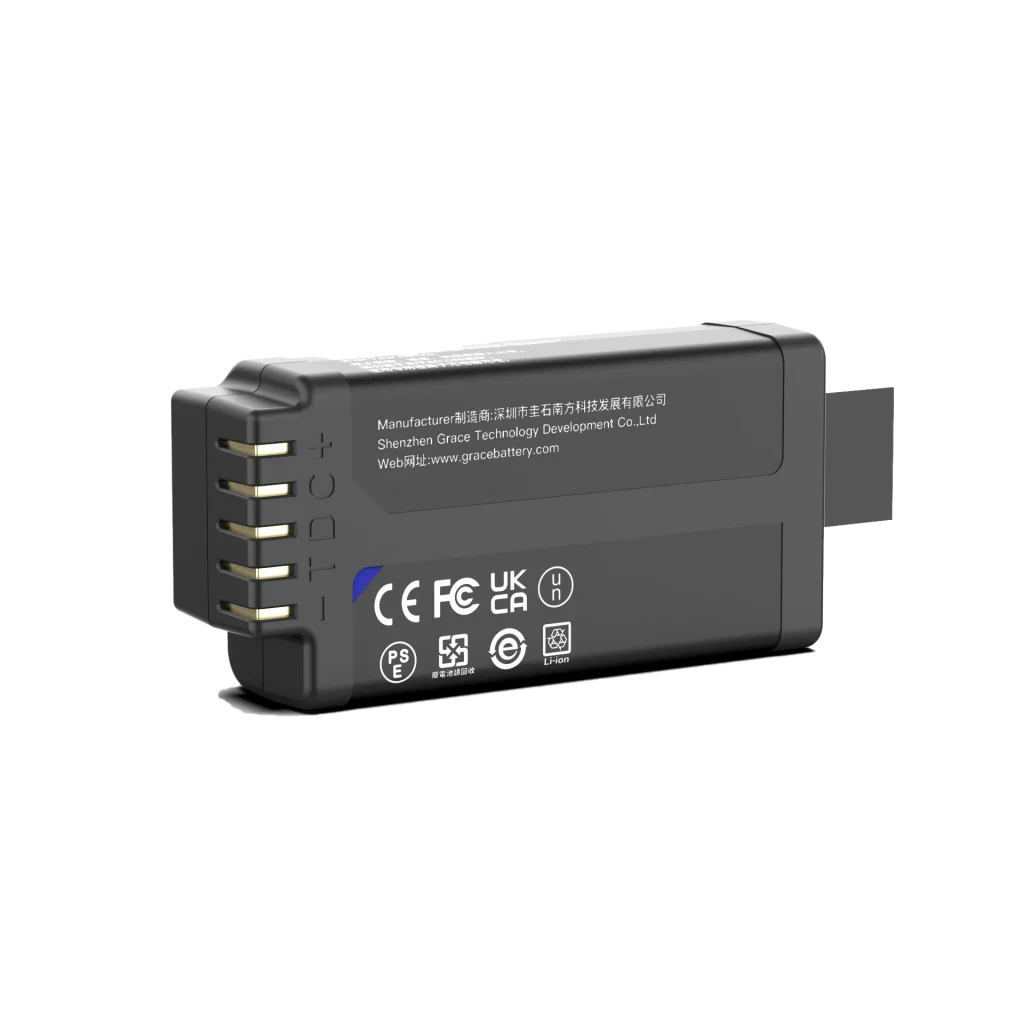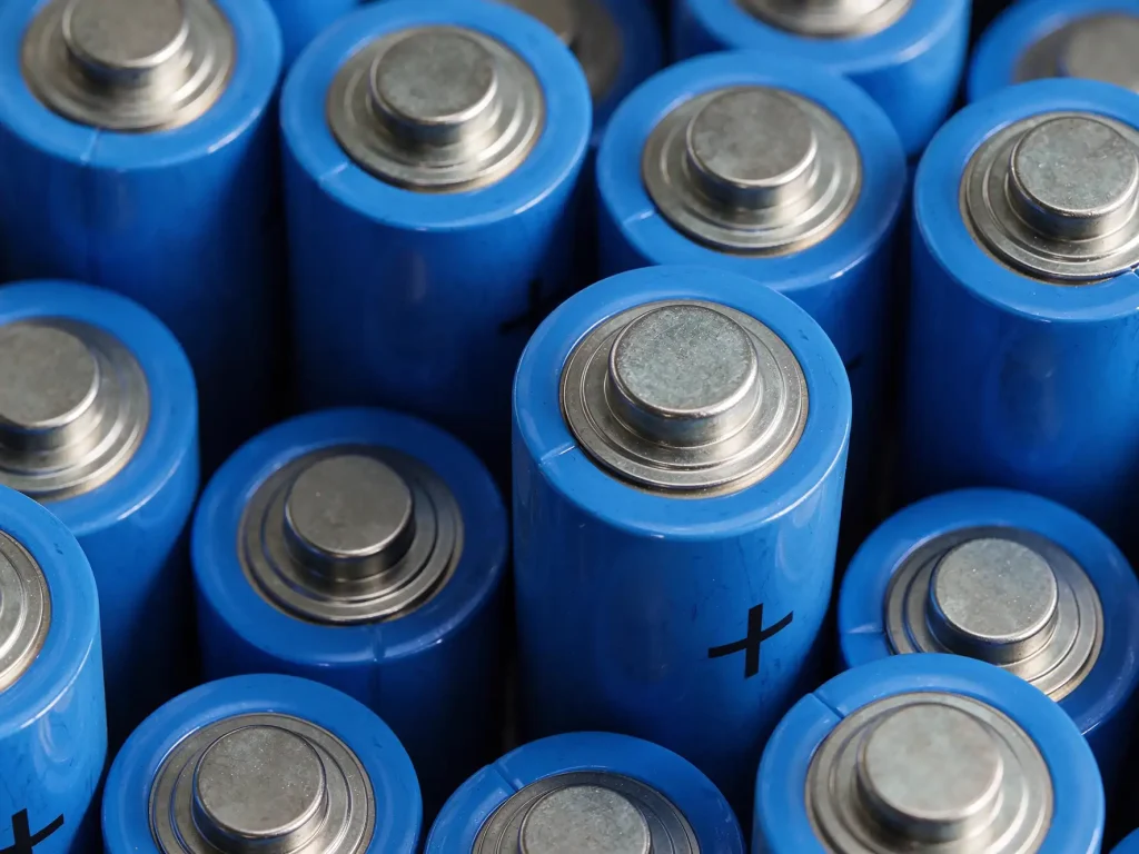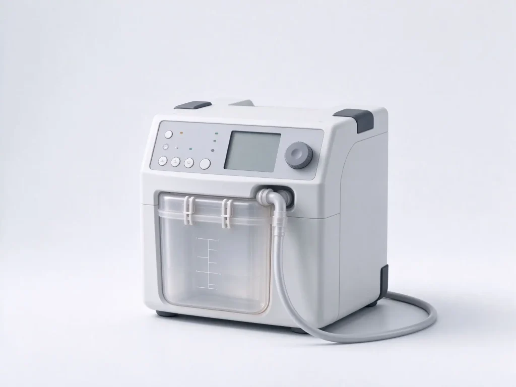
Engineering reference for OEM device teams specifying smart lithium-ion packs for industrial, environmental, medical and handheld diagnostic sensors.
1. Introduction
A portable sensor battery pack is the rechargeable energy source that keeps handheld, wearable, field-deployed and wireless sensor instruments running away from fixed mains power. In the context of modern sensing equipment, the pack is rarely a simple battery holder: it is an engineered subsystem of cells, a battery management system (BMS), a fuel gauge, temperature sensing, protection circuitry, enclosure, connector and, in most professional-grade products, a digital communication interface that reports remaining capacity and battery health to the host device.
For sensor OEMs, the battery pack determines runtime between charges, measurement continuity in the field, product weight and ergonomics, field-service behavior, and the ability to pass market-entry safety and transport certifications. A poorly specified pack can cause unexpected shutdowns mid-measurement, inaccurate state-of-charge (SOC) readouts, reduced cycle life, or certification delays at the end of the development cycle.
This guide is written from the perspective of a senior lithium-ion battery R&D engineer supporting OEM projects. It defines what a portable sensor battery pack consists of, the engineering requirements that drive its design, the cell chemistries and communication protocols commonly selected, the safety and regulatory certifications required for major markets in 2026, and a structured selection framework buyers can use when briefing a pack manufacturer. Recommendations are engineering-oriented and should be confirmed against the final device specification, target markets and applicable product-risk file.
2. What Is a Portable Sensor Battery Pack?
A portable sensor battery pack is a secondary (rechargeable) battery assembly purpose-built to power a sensor device that operates on battery energy for extended periods, often outside a controlled laboratory environment. Unlike a consumer power bank, the pack is designed around the host instrument’s voltage window, current profile, mechanical envelope, temperature range and communication requirements rather than around generic USB output.
2.1 Typical Subsystems
- Cells: one or more lithium-ion or lithium-polymer cells selected for capacity, voltage, energy density, cycle life and safety profile.
- Battery management system (BMS): protection circuitry for overcharge, over-discharge, overcurrent, short circuit and temperature extremes; cell balancing where series strings require it.
- Fuel gauge / gas gauge: SOC estimation, state-of-health (SOH) tracking, remaining run-time prediction and, where supported, authentication against the host device.
- Sensing and feedback: NTC thermistor or internal temperature sensors, voltage and current measurement, and alarm or alert outputs where the host requires them.
- Mechanical and electrical assembly: enclosure, potting or structural protection, cell holder or weld pack, connector, contact pads, label, ventilation and structural isolation for shock and vibration.
- Communication interface: SMBus, I2C, UART, CAN or another protocol through which the host firmware reads SOC, SOH, cell voltages, current, temperature and fault flags.
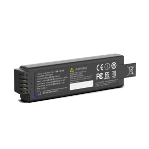
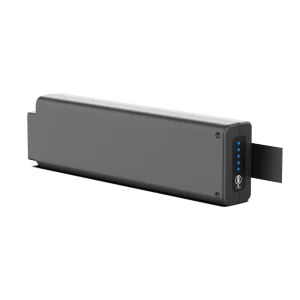
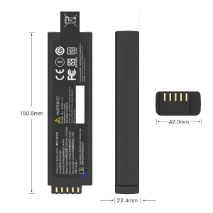
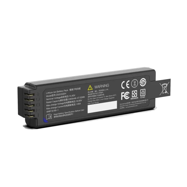
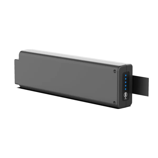
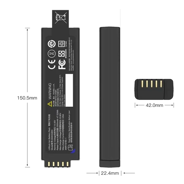
GS2034DH
14.4V/3450mAh/47.52Wh
3. Common Application Scenarios
Portable sensor battery packs appear wherever a measurement instrument must be carried, mounted on a wearable, left in the field, or deployed where mains power is unavailable. Requirements vary strongly by scenario, and the pack should be specified against the actual operating environment rather than copied from a generic consumer battery design.
| Application scenario | Representative devices | Typical power considerations |
| Industrial & process monitoring | Handheld gas analyzers, vibration sensors, pressure sensors, data loggers, survey instruments | Wide operating temperature, vibration resistance, sustained current pulses, long calendar life, robust enclosure |
| Environmental & field sensing | Water quality monitors, air-quality meters, weather stations, soil sensors, GPR and geophysical instruments | Low quiescent current, long standby, intermittent high-current sampling, outdoor temperature and humidity tolerance |
| Medical & point-of-care diagnostics | Patient monitors, infusion pumps, portable defibrillators, handheld diagnostics, wearable medical sensors | High safety margin, accurate SOC/SOH, traceability, medical quality system support, compliance with device-level risk file |
| Wearable & handheld devices | Wearable monitoring patches, portable testers, handheld inspection tools | Low weight and thickness, rounded enclosure, controlled surface temperature, ergonomic contact design |
| Wireless IoT & remote sensing | LoRa/Bluetooth/Wi-Fi sensor nodes, remote monitoring probes | Low self-discharge, efficient sleep mode, capacity matched to duty cycle, optional rechargeable or long-life design |
Table 1. Typical portable sensor battery pack application scenarios and power considerations
4. Core Design Requirements
A reliable pack design begins with a requirements capture from the host device. The following parameters should be fixed before cell selection and BMS configuration, because each one constrains the others.
4.1 Voltage and Capacity
Nominal pack voltage is determined by the host’s operating voltage window and regulator topology. Series cell configurations (e.g., 1S, 2S, 3S, 4S) define the nominal voltage and the BMS’s series-protection requirements. Capacity, rated in ampere-hours (Ah) or milliampere-hours (mAh), should be derived from measured or simulated runtime: average current, peak pulse current, duty cycle, target runtime between charges, and acceptable end-of-life capacity retention. Capacity should not be inflated to a marketing number; it must remain usable within the host’s cutoff voltage.
4.2 Current Profile and Pulse Load
Sensors often draw low quiescent current most of the time but produce peak pulses when transmitting, activating a pump, heating a sample chamber, or driving a display and actuator together. The pack’s continuous discharge rating and peak-current capability must cover the worst-case pulse with margin, and the BMS current-limit threshold must be set so normal pulses do not trigger nuisance cutoff. Conversely, an over-rated pack adds weight, cost and volume for no benefit.
4.3 Runtime, Cycle Life and Calendar Life
Runtime is the result of usable capacity and current draw, not of nameplate capacity alone. Cycle life depends on depth of discharge, charge/discharge rates, temperature and the voltage window the BMS enforces. Calendar life refers to capacity retention over time regardless of cycling; packs stored for long standby periods need a low self-discharge design and, where relevant, a storage SOC specification agreed between the OEM and the battery manufacturer.
4.4 Operating Temperature and Environmental Protection
Charge and discharge temperature windows should be matched to the field environment. Most standard lithium-ion cells should not be charged below 0 C; low-temperature charging can cause lithium plating and irreversible capacity loss. Discharge at elevated temperature accelerates aging. Enclosure protection, ingress resistance, vibration, drop, shock and chemical exposure should be specified according to the device’s intended use and the applicable device-level standard.
4.5 Weight, Form Factor and Ergonomics
In handheld and wearable sensors, pack weight and thickness directly affect user acceptance. Energy density, cell form factor (cylindrical, prismatic or pouch), mechanical structure and connector arrangement must be balanced against safety margin, heat dissipation and serviceability. Hot-swappable packs, where required, add latch, contact and redundancy constraints to the mechanical design.
5. Cell Chemistry Selection
The most common rechargeable chemistries for professional sensor packs are lithium-ion NMC/NCA-type cells, lithium-polymer pouch cells, and lithium iron phosphate (LiFePO4/LFP) cells. The choice depends on voltage, energy density, cycle life, temperature behavior, safety priorities and certification target.
| Chemistry | Typical strengths | Typical limitations | Common fit in sensor packs |
| NMC / NCA cylindrical or prismatic Li-ion | High energy density, mature supply chain, broad form factors, good nominal voltage per cell | More sensitive to abuse and high temperature; requires robust BMS protection | Handheld analyzers, portable medical and diagnostic devices, compact high-runtime instruments |
| Lithium-polymer pouch | Thin and flexible form factor, low profile, customizable shape, good packaging efficiency | Pouch integrity and swelling control needed; mechanical protection important | Wearables, slim handheld tools, space-constrained enclosures |
| LiFePO4 (LFP) | Strong cycle life and thermal stability, wider discharge tolerance, robust abuse profile | Lower energy density per volume/weight, lower nominal cell voltage | Stationary field loggers, long-life remote sensors, duty cycles favoring cycle durability |
Table 2. Rechargeable cell chemistry comparison for portable sensor battery packs
Chemistry selection should be documented in the design file together with the rationale, cell data sheet, lot traceability and the safety analysis. Where the device is used near patients or in an enclosed wearable enclosure, the safety case should justify the chemistry, thermal design and protection redundancy rather than rely on general industry assumptions.
6. Smart BMS and Host Communication
Professional sensor packs increasingly use a smart BMS rather than a bare protection circuit. The smart subsystem protects the cells, estimates SOC and SOH, records fault history, and communicates structured battery data to the host firmware so the device can manage runtime, alert the user before shutdown, and support predictive maintenance.
6.1 Baseline Protection Functions
| Protection function | Purpose | Engineering note |
| Overcharge protection | Stops charging when any cell reaches the upper voltage limit, preventing lithium plating and thermal stress | Threshold and recovery must match the cell manufacturer’s charge specification |
| Over-discharge protection | Cuts the discharge path when a cell drops below the lower cutoff, preventing irreversible damage | Host low-battery warning should trigger before the BMS hard cutoff |
| Overcurrent protection | Limits or disconnects discharge current above the rated continuous or peak threshold | Threshold must distinguish normal sensor pulses from real faults |
| Short-circuit protection | Hardware-level response on an external short circuit | Response time and FET rating should be verified against the pack design |
| Temperature protection | Monitors NTC/internal sensors; inhibits charge or discharge outside allowed temperature bands | Charge inhibition at low temperature is a key safety requirement for Li-ion cells |
| Cell balancing | Equalizes cell voltage in series strings during charge or at rest | Relevant where multiple cells are in series and imbalance affects usable capacity |
Table 3. Baseline BMS protection functions for sensor battery packs
6.2 Fuel Gauge and SOC/SOH Reporting
A fuel gauge estimates SOC from voltage, current and temperature data, using algorithmic models or impedance-tracking-type methods, and tracks SOH by comparing present capacity against the original rated capacity. Reported accuracy, aging compensation and recovery behavior should be validated against the actual host current profile. The host device should consume SOC and SOH through the defined interface rather than inferring remaining runtime from pack voltage alone, which is unreliable under changing pulse loads.
6.3 Communication Interfaces
- SMBus: widely used in smart battery systems; the host reads voltage, current, SOC, SOH, temperature and cell-level data over a two-wire interface, commonly specified for medical and professional instrument packs.
- I2C: lightweight two-wire interface suitable for simple data exchange where the smart-pack feature set is limited.
- UART: flexible serial interface for custom firmware reporting and diagnostic data, common in custom OEM designs.
- CAN / CANopen / RS-485: used in industrial and multi-device environments where noise immunity and longer wiring runs matter.
The protocol, register map, baud rate, alert behavior and authentication scheme must be agreed between battery supplier and device firmware team early in the project. Interface mismatch discovered late in integration is a common cause of delayed product release.
6.4 Authentication and Security
Higher-risk medical or professional devices may require pack authentication so the host can verify an authorized battery and prevent unqualified replacement packs from being used. Authentication schemes, key management and the host-side reaction to an unauthorized pack should be defined in the device security and risk requirements.
7. Safety, Certification and Regulatory Compliance
Certification requirements depend on the product category, target market and whether the pack is shipped separately or inside the host device. The table below summarizes the battery- and product-level requirements most frequently encountered for portable sensor packs in 2026. Final applicable standards must be confirmed with the notified body, test laboratory and the device’s regulatory consultant, because medical devices, radio equipment and professional industrial equipment each carry additional product-level obligations.
| Requirement | Scope | Typical relevance to sensor packs |
| IEC 62133-2 | Safety requirements for portable sealed secondary lithium cells and batteries used in portable applications | Core international safety standard for many portable Li-ion packs; test evidence is often required for market entry |
| UN 38.3 | United Nations transport test protocol for lithium cells and batteries | Required for transport (including air transport) of lithium batteries; covers altitude, thermal, vibration, shock, short circuit and abuse-related tests |
| UL 1642 / UL 2054 | North American safety standards for lithium cells and battery packs | Frequently referenced for North American market access and by device-level certification |
| CE marking | EU conformity framework covering applicable directives/regulations | Required when placing the product on the EU market; applicable low-voltage, EMC, radio and device rules depend on the host |
| UKCA | UK conformity marking | Required for relevant products placed on the Great Britain market |
| FCC | US electromagnetic interference rules for electronic equipment | Applies to the host device where radio or digital circuitry is present; the pack design should not introduce interference |
| CB scheme / IEC test reports | International test-report acceptance framework | Supports multi-market certification with reduced repeated testing |
| ISO 13485 | Medical device quality management system | Relevant when the pack supplies a medical device; supports traceability, controlled production and documentation for the device quality file |
| ISO 9001 / ISO 14001 | General quality management and environmental management systems | Common supplier-level expectations for OEM battery supply |
| EU Regulation 2023/1542 | EU batteries and waste batteries regulation covering sustainability, labeling, due diligence, removability/replaceability and end-of-life | Applies to batteries placed on the EU market; labeling, documentation, recycled-content and future replaceability obligations should be reviewed against the product category and transition dates |
| RoHS / REACH | Restriction of hazardous substances and chemical regulation | Material declarations and restricted-substance compliance are typically required for electronics placed on EU/EEA markets |
| KC / PSE / BSMI | Market-specific conformity schemes for Korea, Japan and Taiwan | Applicable when those markets are targeted; requirements should be checked per destination |
| IEC 60601-1 / ISO 14971 (medical) | Medical electrical equipment safety and risk management | Device-level requirements; the battery supplier should provide documentation supporting the manufacturer’s risk file and clinical/technical evaluation |
Table 4. Common safety, quality and regulatory requirements for portable sensor battery packs (2026)
Documentation traceability matters as much as the certificates themselves: cell lot records, BMS firmware version, test reports, material declarations, MSDS/safety documentation and change-notification procedures should be available for the OEM’s device file. For medical and regulated instruments, the battery supplier’s quality-system support and ability to maintain a stable, documented production configuration are often as important as the headline specifications.
8. Selection Criteria for OEM Buyers
When comparing pack suppliers or off-the-shelf solutions, evaluate the pack against the host specification rather than price alone. The following checklist provides a structured basis for technical review.
8.1 Technical Checklist
- Nominal voltage, usable capacity, continuous and peak discharge current matched to the measured device load profile.
- Cell chemistry and cell form factor justified by energy density, cycle life, temperature range and safety priorities.
- BMS protection thresholds, recovery behavior, balancing strategy and fault-logging capability.
- Fuel gauge accuracy, SOH algorithm, aging compensation and how SOC is exposed to the host.
- Communication protocol, register map, electrical interface, alert pins and authentication scheme.
- Operating and storage temperature windows, enclosure rating, shock, vibration and drop performance.
- Mechanical envelope, weight, connector, latch, hot-swap behavior and service replacement plan.
- Charge method, charger compatibility, standby self-discharge and recommended storage SOC.
8.2 Compliance and Supply Checklist
- Relevant cell and pack certificates, test reports and market-access evidence for every target country.
- Quality system evidence (e.g., ISO 9001; ISO 13485 where the pack supports a medical device) and environmental management evidence.
- Cell and component traceability, change-control policy and notification of supplier or material changes.
- Documentation package available for the device technical file: datasheet, test reports, material declarations, BMS configuration, firmware revision and safety analysis.
- Manufacturing capacity, sample lead time, production ramp plan, acceptance criteria and field-support process.
8.3 Typical Selection Workflow
- Step 1: Capture host requirements: load profile, runtime, envelope, temperature, interface, target markets and risk category.
- Step 2: Derive pack architecture: cell count, series/parallel configuration, chemistry, BMS feature set and communication interface.
- Step 3: Request supplier proposal with cell data, BMS configuration, certification evidence and validation plan.
- Step 4: Validate engineering samples under the real duty cycle, temperature range and communication test cases.
- Step 5: Lock the design, documentation and production control before certification and volume release.
9. OEM Customization and Manufacturing Considerations
Most professional sensor instruments require a degree of pack customization: custom cell arrangement, enclosure geometry, connector, protocol adaptation or firmware reporting. A custom OEM pack should be treated as an engineering project with defined design inputs, design outputs, verification and traceability.
- Cell selection and lot control: specify the cell grade and supplier, and retain lot-level records linking finished packs to cell batches.
- BMS firmware: record firmware version, protection thresholds, balancing settings and any custom gauge parameters.
- Design history: keep the pack design rationale, risk analysis, test data and change history accessible for the host device file.
- Production controls: confirm assembly process, welding or connection method, incoming inspection, end-of-line test and outgoing quality criteria.
- Validation: test runtime, pulse behavior, charge/discharge temperature cycle, communication stability and fault recovery under representative conditions before production release.
For regulated devices, clarify early whether the battery supplier can provide documentation that supports the host manufacturer’s design history file (DHF), device master record (DMR) or equivalent technical file, and whether the supplier can manage controlled changes over the product lifetime.
10. Common Design Pitfalls
- Underestimating pulse current: a pack sized only for average current can cut out during transmission, actuation or display peaks.
- Charging at low temperature: allowing charge below the cell’s specified minimum without BMS inhibition can cause lithium plating and shortened life.
- Ignoring cell imbalance: series strings without appropriate balancing drift in capacity and voltage, reducing usable runtime and safety margin.
- Assuming voltage equals SOC: a voltage-only fuel estimate is inaccurate under changing loads; a proper gauge and defined host interface are needed.
- Leaving certification late: transport and safety testing, plus product-level compliance, should be planned into the development schedule rather than added after the prototype is frozen.
- Overlooking documentation: a pack that performs well in the lab but lacks traceability, test reports and controlled firmware can delay regulated product release.
11. Frequently Asked Questions
Q: What is a portable sensor battery pack?
A: It is a rechargeable battery assembly engineered to power a portable, handheld, wearable or field-deployed sensor device. It typically includes cells, a BMS, protection circuitry, temperature sensing, a fuel gauge, enclosure and a host communication interface, rather than being a plain battery holder.
Q: Which battery chemistry is best for a handheld sensor?
A: There is no single best chemistry. NMC/NCA Li-ion and lithium-polymer pouch cells usually offer the best energy density and compactness for handheld devices; LFP is preferred where cycle life and thermal stability outweigh energy density. The choice should follow the measured load, runtime, envelope, temperature range and safety analysis.
Q: Do sensor packs need a smart BMS?
A: Not every simple logger requires a full smart BMS, but professional, medical or multi-function sensors usually benefit from one: it protects the cells, estimates SOC and SOH, logs faults and reports battery status to the host firmware. A bare protection board provides basic safety but limited diagnostic information.
Q: What does SMBus mean for a sensor battery pack?
A: SMBus is a two-wire serial interface commonly used in smart battery systems. It allows the host device to read pack voltage, current, SOC, SOH, temperature and fault data, and to coordinate charging and low-battery warnings. The protocol and register map must be agreed with the device firmware team.
Q: Which certifications are usually required?
A: Common requirements include IEC 62133-2 for portable lithium battery safety, UN 38.3 for transport, and market-specific evidence such as UL 1642/2054 in North America, CE/UKCA in Europe and the UK, and local schemes such as KC, PSE or BSMMI where those markets are targeted. Medical devices also rely on the manufacturer’s device-level risk and quality documentation. The exact list depends on the product and destination.
Q: How do I estimate the required pack capacity?
A: Derive capacity from the device’s current profile: average current, peak pulses, duty cycle, target runtime, acceptable end-of-life retention and the host’s cutoff voltage. Do not rely only on nameplate mAh; verify with measured or simulated runtime data and validate on engineering samples.
Q: Can a standard consumer battery be used in a professional sensor?
A: A consumer pack may be suitable for low-risk, simple devices, but professional and regulated instruments generally need a pack designed for the specific load, mechanical envelope, temperature range, interface and compliance evidence. Reusing an unverified consumer pack risks runtime mismatch, poor SOC reporting, safety concerns and certification gaps.
Q: What should an OEM request from a battery pack manufacturer?
A: Request cell and pack datasheets, BMS configuration, protection thresholds, gauge description, communication protocol, relevant certificates and test reports, material declarations, traceability and change-control policy, plus a sample validation plan covering runtime, pulses, temperature and interface behavior.
12. Conclusion
A portable sensor battery pack is a core engineering subsystem, not a commodity accessory. Its performance is determined by how well the cell chemistry, capacity, BMS, fuel gauge, communication interface, mechanical design and compliance documentation are matched to the host instrument’s real load profile and operating environment. Specifying the pack early, validating it against the actual duty cycle, and securing traceable certification evidence reduce the risk of field shutdowns, inaccurate battery readouts and late-stage compliance delays.
For OEM teams preparing a new sensor product, the most effective approach is to treat the battery pack as a co-engineered subsystem: define electrical, mechanical, thermal, interface and regulatory requirements up front, engage the battery supplier during architecture planning, and keep the design, test and production documentation aligned with the host device’s technical file.
13. Author and Editorial Note
This article was prepared from the perspective of a senior lithium-ion battery R&D engineer supporting OEM sensor and instrument projects. It provides general engineering guidance on pack architecture, BMS features, chemistry trade-offs and commonly encountered compliance requirements. It does not replace a product-specific safety analysis, regulatory assessment or third-party certification. Final cell selection, BMS settings, certifications and documentation must be confirmed against the host device specification, target markets, applicable standards and the advice of qualified test laboratories and regulatory consultants.
Standards and regulation evolve; any requirement mentioned here should be checked against the current official text and the applicable conformity route at the time of product release.