Technical Blog · Battery System Engineering for Tactile Sensing Devices · Prepared by a Senior Lithium Battery R&D Engineer
1. Introduction
A tactile sensor measures pressure, force, shear, vibration, temperature or texture, and translates that interaction into an electrical signal that a microcontroller, prosthetic controller or robotic system can use. Whether the device is an electronic skin (e-skin) on a humanoid robot, a pressure-sensing patch on a prosthetic hand, a wearable haptic band or a handheld diagnostic probe, the power source is often the component that most tightly defines its operating time, comfort, safety and clinical or commercial acceptance. A tactile sensor power battery is not, however, a generic lithium pack: it must deliver stable low-voltage rails to sensitive analog front ends, survive repeated mechanical deformation, sit inside a small or flexible enclosure, and meet the transport, safety and market-access rules of the destination region.
This guide is written from the perspective of a senior battery R&D engineer who has designed smart battery systems for portable medical and industrial instruments. It explains what a tactile sensing system actually draws from its battery, how chemistry and pack architecture are selected, what protection and communication features matter, which certifications are typically required, and how OEM teams should evaluate a candidate pack. Throughout, the focus is on engineering decisions that are verifiable rather than marketing claims: current profiles, voltage tolerance, cycle life, thermal behavior and documented compliance.
Core takeaway: the best tactile sensor power battery is the one matched to the device’s duty cycle, mechanical form, communication bus and regulatory target in that order. A pack chosen only by nominal voltage or capacity will usually undersize runtime, oversize weight or miss a certification requirement.
2. What a Tactile Sensor System Actually Draws
Before selecting a battery, the power engineer must measure the load profile of the complete device, not the sensor cell alone. A tactile sensing system typically contains the sensing array or nodes, an analog front end or signal-conditioning circuit, a microcontroller, a wireless or wired communication link, and sometimes a small actuation or feedback module. Each block contributes a different current pattern.
2.1 Typical current states
- Sleep or standby: the controller keeps interrupts and wake-up logic alive while the sensor array idles; current is usually in the microamp to low-milliamp range, and this state often dominates overall energy consumption between active interactions.
- Sampling and signal conditioning: nodes scan at a defined sampling frequency. Literature on multi-sensory e-skin reports average node latency on the order of 12 ms, and active node current rises with array density, resolution and refresh rate.
- Processing and classification: local inference or object identification on the device adds compute peaks; event-driven or neuromorphic architectures can keep median inference power very low, while continuous streaming raises average current.
- Communication: radio transmission is usually the highest instantaneous load. Bluetooth Low Energy, proprietary RF or wired buses draw short, high-current bursts, and the battery must support these peaks without an unacceptable voltage sag.
- Actuation or feedback: haptic drivers, vibration motors or electro-active elements on a patch add pulsed current and may require a separate regulated rail.
2.2 Voltage and array-scale considerations
Many flexible and printed tactile sensors operate at very low signal levels; reported soft sensors can run below 1 V, while the host controller and radio commonly use 3.3 V or 1.8 V rails. The battery therefore works through a power-management stage, and pack design must account for conversion losses, ripple and noise that can degrade measurement resolution. At the other end of the scale, large-area e-skin with thousands of distributed nodes, actuators and on-body electronics becomes comparatively power-hungry: review literature indicates that large sensor networks can require power on the order of several watts, and some hand or finger prototypes use small rechargeable packs around 1000–1200 mAh to deliver several hours of continuous operation.
The practical engineering output of this stage is a current-versus-time budget: standby current, active current, peak current, average current, expected duty cycle and target runtime. Capacity is derived from average energy consumption and the chosen margin; peak current and end-of-discharge voltage drive the protection and cell sizing, not the headline capacity figure.
3. Why a Standard Battery Pack Does Not Fit a Tactile Sensor Device
Off-the-shelf consumer packs are designed for a stable load and a standard enclosure. Tactile sensing devices differ in four ways that force a custom or application-optimized pack.
- Mechanical coupling: sensors often conform to a finger, a curved limb, a garment or a robot palm. The pack must share that envelope, which may mean a thin prismatic form, a flexible or curved architecture, or a small cylindrical coin cell placed away from the flexible sensing area.
- Sensitive analog environment: measurement circuits are sensitive to supply noise and voltage droop. The pack and its protection circuit must avoid transients that corrupt force or pressure readings.
- Distributed or wearable placement: weight, thickness, skin contact, sweat, cleaning and bend cycles all constrain enclosure and insulation choices that a desk-bound consumer product ignores.
- Regulatory context: when the device touches the body, supports a clinical decision or travels internationally, the battery must sit inside a documented quality system and meet transport and market-access standards rather than a generic consumer listing.
4. Battery Chemistry and Pack Selection
Chemistry choice is a trade-off between energy density, self-discharge, cycle life, operating temperature, safety profile and shelf life. The following comparison summarizes the options most often considered for tactile sensor products.
| Chemistry / Format | Typical Use | Strengths | Watch-outs |
| Lithium-polymer pouch (Li-Po) | Wearable patches, handheld probes, small e-skin controllers | Thin, formable prismatic shapes; moderate energy density; proven low-voltage support | Needs mechanical protection against puncture; cycle life and low-temperature performance depend on cell selection |
| Rechargeable Li-ion (cylindrical / prismatic) | Robotics and handheld devices with longer runtime | High energy density; mature supply chain; wide range of protected modules | Less conformable; protection circuit and enclosure still required |
| Primary lithium (Li-SOCl₂ / Li-MnO₂) coin or cylindrical | Ultra-low-power sensors, long shelf life, disposable devices | Very low self-discharge; long shelf life; stable voltage plateau | Non-rechargeable; disposal and recycling rules differ; no charge-cycle design |
| Zinc-ion / emerging micro-battery | Research-grade flexible, thin-form integrated systems | Flexible, potentially printable; recent prototypes integrate directly with sensor arrays | Maturity, supply chain and certification are less established for volume OEM use |
| Coin cell with holder | Ultra-compact, low-duty-cycle modules | Low cost, small volume, easy swap-out | Limited peak current; holder contact reliability over vibration and bending |
For a rechargeable wearable or medical-adjacent product, a protected lithium-polymer pack is usually the default starting point, because it balances form flexibility and energy density. For a sensor that spends most of its life in standby, a primary lithium chemistry may be more reliable than a small rechargeable pack that cycles infrequently and suffers self-discharge. Any novel or flexible chemistry should be evaluated not only on laboratory energy figures but also on volume production, traceability and the ability to obtain the safety documentation the target market requires.
5. Core Engineering Design Requirements
5.1 Smart BMS and protection
A rechargeable tactile sensor pack should include a battery management system (BMS) matched to the cell count and load. Minimum protection functions typically include overcharge, overdischarge, overcurrent, short-circuit and temperature monitoring, with a reliable recovery strategy that does not leave the handheld or wearable device unexpectedly disabled. For multi-cell packs, cell balancing prevents drift across cycles; for single-cell designs, the protection focus is on discharge cutoff, charge cutoff and thermal shutdown. A smart BMS can also report state of charge, state of health and cycle count to the host, which is valuable for field service and for medical-adjacent traceability.
5.2 Power rails, regulation and low-voltage compatibility
The pack voltage and the system regulator must be chosen together. Confirm the minimum input voltage the regulator accepts, the dropout margin under peak radio current, and the ripple budget at the sensor analog input. Sizing the pack only for nominal voltage can leave insufficient headroom as the cell discharges; the design should stay valid at end-of-discharge, not just at a fresh charge. Capacitance placement and layout on the host side matter as much as the pack itself, because a noisy rail can look like a false tactile reading.
5.3 Communication: SMBus, I²C or proprietary
Where the host needs fuel-gauge data, the pack may use SMBus, I²C or a proprietary two-wire protocol. SMBus is common in smart rechargeable packs and supports voltage, current, state-of-charge and temperature reads; I²C is lighter for simple gauge circuits; proprietary lines remain common in compact OEM modules. The protocol should be fixed early in the project, because it defines the BMS firmware, the host driver and the data format exchanged over the device life cycle. Cable or flex-wire count, connector reliability and sleep-state wake-up behavior should all be validated in the actual mechanical assembly.
5.4 Mechanical form factor and conformability
Work from the device envelope backwards: thickness at the sensor contact area, available volume away from the flex zone, weight on the body or limb, and fastener or bonding method. The pack should be protected against bending, compression and sweat; insulation and enclosure materials must be compatible with skin contact and any cleaning or disinfection process. For curved or wearable designs, separate the flexible sensing region from the rigid battery and electronics housing where possible.
5.5 Thermal, safety and reliability
Tactile devices are handled, worn and sometimes sterilized. The pack should be rated for the expected ambient and enclosed operating temperature, validated against vibration, drop and crush conditions relevant to the use case, and inspected for swelling, seal integrity and connector retention after the target cycle count. Reliability validation should cover charge-discharge cycling, storage at high and low temperature, and the aging of insulation and enclosure materials.
6. Application Scenarios and Design Emphasis
| Scenario | Power Profile | Battery Design Emphasis |
| Humanoid / robotic e-skin | Dense node array, continuous scanning, radio or bus data, possible actuation | Capacity matched to node count and runtime; stable rail under transmission peaks; robust protection against crush and vibration |
| Prosthetic hand or neuroprosthesis | Intermittent grasp and touch events; long standby; user comfort | Light weight, compact volume, reliable wake-up, predictable remaining capacity, documented quality system |
| Wearable haptic or sensing patch | Body-worn, flexible, event-driven bursts, periodic wireless transmission | Thin profile, sweat and cleaning resistance, low standby current, safe skin-contact materials |
| Handheld diagnostic or sensing probe | Intermittent use over a shift, occasional peak load | Protected rechargeable pack or swappable primary cell, clear fuel gauge, rugged enclosure, serviceable connector |
7. Selection Criteria for Evaluating a Tactile Sensor Power Battery
When comparing pack options or requesting an OEM quotation, evaluate each candidate against the same measurable dimensions. The table below is a practical scoring checklist; weight each row according to the device’s own priority.
| Dimension | What to Verify | Evidence to Request |
| Capacity and runtime | Average current, peak current, target runtime and margin at end-of-discharge | Load-current profile, calculated runtime, cell capacity and rated energy |
| Voltage compatibility | Nominal, charge and cutoff voltage against regulator and sensor rails | Discharge curve, regulator dropout check, peak-load sag measurement |
| Protection | Overcharge, overdischarge, overcurrent, short circuit, temperature | BMS schematic or function list, protection thresholds, recovery behavior |
| Communication | SMBus / I²C / proprietary data points and host driver | Protocol specification, gauge data format, sample host code or register map |
| Mechanical fit | Dimensions, weight, thickness, bend or curve allowance, connector | Mechanical drawing, 3D model, enclosure and insulation materials |
| Safety and certification | Cell and pack standards, transport and destination-market approvals | Test reports, certificates, standard numbers and validity dates |
| Quality system | Traceability, change control, manufacturing documentation | Quality audit records, cell traceability, incoming inspection and change-notice process |
| Environmental and life | Cycle life, storage, operating temperature, aging | Cycle test data, storage condition report, material compatibility notes |
8. Compliance and Certification to Plan For
Certification planning should begin at cell selection, because reworking an approved pack after prototype integration is costly. The exact set of requirements depends on the device classification and destination region; the standards below are the ones most commonly encountered for portable rechargeable and primary lithium batteries in tactile sensing, wearable and medical-adjacent equipment.
- IEC 62133-2: safety requirements for portable sealed secondary lithium cells and batteries; covers abuse and mechanical/electrical stress testing at cell and pack level.
- UL 1642 (lithium cells) and UL 2054 (household and commercial battery packs): common North American safety references for battery packs used in portable equipment.
- UN 38.3: transportation safety testing for lithium cells and batteries, required before shipping lithium batteries by air, sea or road; test summary must accompany the shipment record.
- ISO 13485: quality management system relevant where the battery supplies a medical device; design, traceability, supplier control and change notice procedures should be documented under the device’s quality file.
- IEC 60601-1: safety and essential performance framework for medical electrical equipment; the battery contributes to risk management and reliability, even though the battery standard itself is separate.
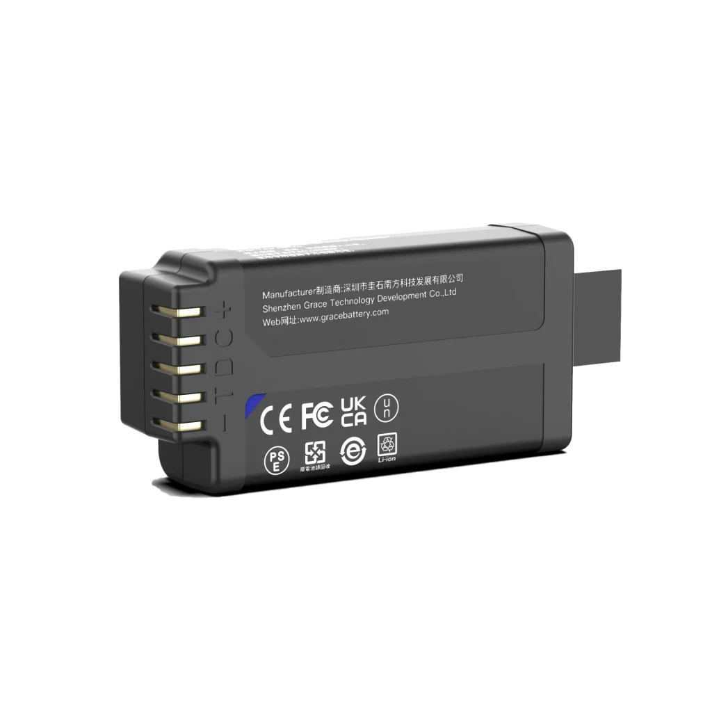
- Regional market access: CE marking under applicable EU legislation, UKCA for the United Kingdom, FCC for radio-emitting equipment in the United States, KC for Korea, PSE for Japan, BSMI for Taiwan, and CCC where applicable. The EU Battery Regulation (Regulation) 2023/1542 governs placing batteries on the EU market, including labeling, collection, recycling and due-diligence obligations, and should be checked against the product category.
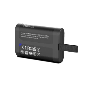
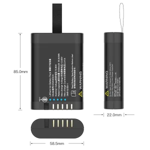
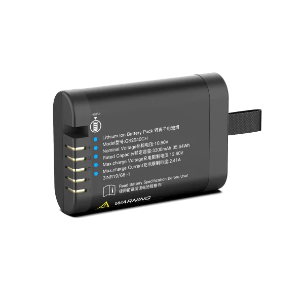
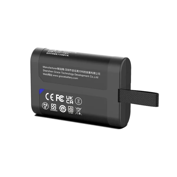
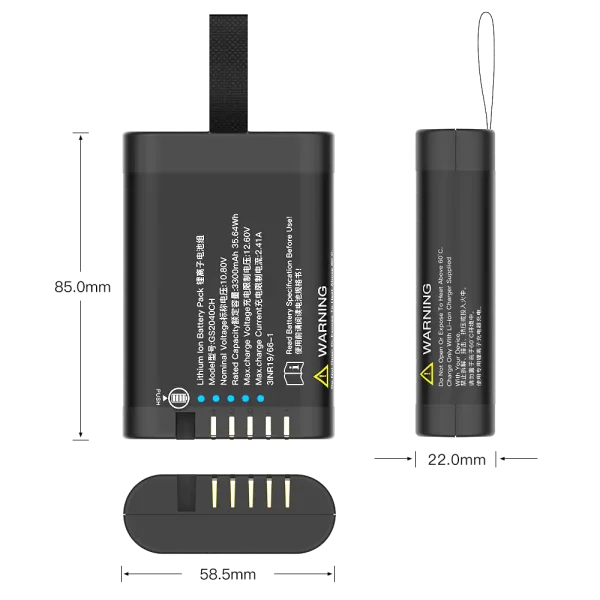
GS2040CH
10.8V/3450mAh/35.64Wh
Do not treat a single cell approval as proof of pack approval. Cell-level and pack-level testing are distinct, and the host device’s own certification may re-evaluate the battery as part of the complete system.
9. Frequently Asked Questions
9.1 What voltage should a tactile sensor battery provide?
There is no single universal voltage. Many sensing elements and front ends operate at low signal levels, while controllers and radios commonly use 1.8 V, 3.3 V or other regulated rails. Define the host rails and regulator input range first, then choose a chemistry and pack that holds voltage above the regulator dropout margin through end of discharge.
How much capacity does a tactile sensor need?
Capacity follows from the measured duty cycle, not from the sensor type alone. Measure standby, active sampling, processing and radio-transmit current separately; average them over the intended operating cycle; divide required energy by usable cell capacity and apply a conservative margin. A low-duty wearable patch may run for weeks on a small pack, while a dense continuous e-skin array may need several watts and a correspondingly larger energy budget.
Is a rechargeable or a primary lithium battery better?
Rechargeable packs suit devices used daily with a defined charging routine. Primary lithium suits ultra-low-duty or long-shelf-life products where frequent charging is impractical. Choose rechargeable only if the device will cycle often enough to justify its BMS and cost; otherwise infrequent charging can expose the rechargeable pack to deep self-discharge and reliability problems.
Does the battery need a smart BMS?
Any multi-cell rechargeable pack and most single-cell wearable packs benefit from protection against overcharge, overdischarge, overcurrent, short circuit and temperature. A smart BMS that reports state of charge and health is recommended where runtime prediction, field service or medical-adjacent traceability matters.
Which communication protocols are used between pack and host?
SMBus is widely used for smart rechargeable packs that report voltage, current, charge and temperature; I²C is a lighter option for simple fuel gauges; proprietary two-wire protocols remain common in compact OEM modules. Fix the protocol during system design, because it affects BMS firmware and host software.
Can a flexible battery be integrated directly into the sensor skin?
Flexible and emerging thin-form batteries exist in research and early products, but integration feasibility depends on bend radius, compression, sweat, cleaning, cycle life and certification maturity. Most volume products still place a protected rigid or semi-rigid pack away from the flexing sensing region, and route power through a flex circuit.
What certifications are mandatory before selling internationally?
UN 38.3 is required for lithium battery transportation. Destination-market safety, radio and product certifications vary: North America commonly references UL standards; the EU applies CE and the EU Battery Regulation 2023/1542; the UK applies UKCA; Korea, Japan and Taiwan apply KC, PSE and BSMI respectively. Medical devices additionally operate under a quality system such as ISO 13485 and risk management under the medical device framework. Confirm the final list with a notified body or certification specialist for the exact device classification.
10. Conclusion
A tactile sensor power battery is a system component, not a commodity accessory. Its design starts from the device’s measured current profile and mechanical envelope, moves through chemistry and BMS selection, and closes with documented protection, communication and compliance. For OEM teams, the most reliable path is to define runtime, voltage rail, form factor, protocol and target markets early, then evaluate pack suppliers against verifiable test reports, standard numbers and a traceable quality system. That approach protects measurement quality, user comfort and product safety, and it gives the device a defensible basis for listing and sale in the intended regions.
References and Public Sources
[1] IEEE Xplore, Large-Area Soft e-Skin: The Challenges Beyond Sensor Designs — energy autonomy analysis for distributed sensor and actuator networks.
[2] SciVision Publishers, A Multi-Sensory Auxetic Electronic Skin with Stretchable Printed Circuits and Physical AI-Based Tactile Intelligence for Humanoid Robots — 3.7 V 1200 mAh lithium-polymer pack and node latency reference.
[3] Science Advances, Skin-attached haptic patch for versatile and augmented tactile interaction (2025) — 1000 mAh rechargeable lithium-ion battery with Bluetooth MCU reference.
[4] Advanced Materials (Wiley), Seconds-Integrated Monolithic System of Zn-Ion Micro-Battery and Multi-Functional Sensors for Robotic Autonomous Tactile Sensing (2026) — integrated micro-battery charging and runtime prototype.
[5] Nanyang Technological University Innovation Portal, A New Generation of Soft Tactile Sensor — sub-1 V soft sensor operating reference.
[6] UL Solutions, Battery Certification Services — UL 1642, UL 2054 and UN 38.3 battery safety and transport references.
[7] IEC 62133-2, Secondary cells and batteries containing alkaline or other non-acid electrolytes — Safety requirements for portable sealed secondary lithium cells and batteries.
[8] EU Regulation 2023/1542 concerning batteries and waste batteries — EU market placement, labeling, collection and recycling obligations.