What makes wireless sensor battery design different
Wireless sensor nodes often spend most of their time asleep, then wake to sample sensors, process data, and transmit a burst over a radio. A low average current can therefore hide a demanding peak-current requirement. Transmit power, antenna conditions, retry behavior, sensor warm-up, cold starts, and firmware update events can all change the load profile. A design based only on average current may estimate runtime correctly in a laboratory demonstration and still suffer brownouts or short field life after deployment.
Before selecting a cell, define the operating profile with measured current and duration for sleep, sensing, processing, radio transmit and receive, joining or reconnecting, and maintenance events. Record the supply voltage at the node as well as current at the battery terminals. Measure the worst credible radio condition, because weak coverage can increase airtime and retries. Include the intended reporting interval, expected network behavior, and any sensor heater, valve, relay, or other high-current load.
1. Translate the duty cycle into an energy budget
A first-order daily charge estimate is the sum of the charge used in each operating state. For state i, multiply its current by its duration and event frequency, then add the state totals:
Q_day (mAh) = Σ [I_i (mA) × t_i (hours/day)]
For brief events, calculate charge per event in mAh and multiply by events per day. Convert charge to energy when voltage changes materially across discharge or a regulator has a defined efficiency curve. Estimate nominal capacity with margin for unusable discharge range, conversion losses, low-temperature behavior, cell aging, self-discharge, and uncertainty in event frequency. Keep those factors visible in the worksheet rather than hiding them inside one arbitrary multiplier.
| Load state | Measure | Why it matters |
| Deep sleep | Current after all sensors and interfaces settle | Long dwell time makes leakage and quiescent current accumulate. |
| Sensor acquisition | Warm-up current, sample duration, event interval | Some gas, optical, and thermal sensors dominate each wake cycle. |
| Radio activity | TX/RX peak, airtime, retries, attach or join events | Peak demand drives voltage sag; coverage changes total energy. |
| Maintenance | Provisioning, firmware update, fault recovery | Infrequent events can be important during commissioning or outages. |
Example: if a node consumes 20 mA for 0.5 seconds every 10 minutes, the radio-related charge is about 0.4 mAh per day before retries and receive windows are included. This is an illustration of the calculation only, not a field-life claim. Measure the actual waveform and event rate for the target network.
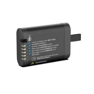
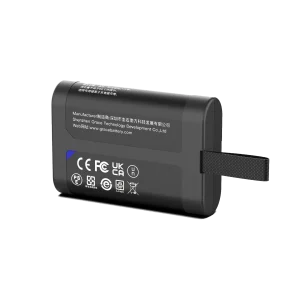
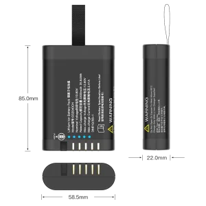
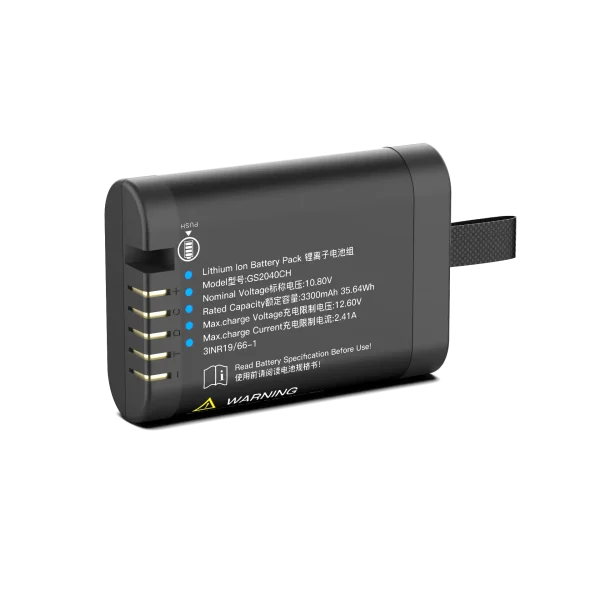
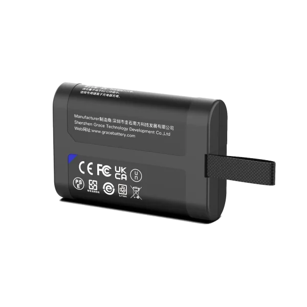
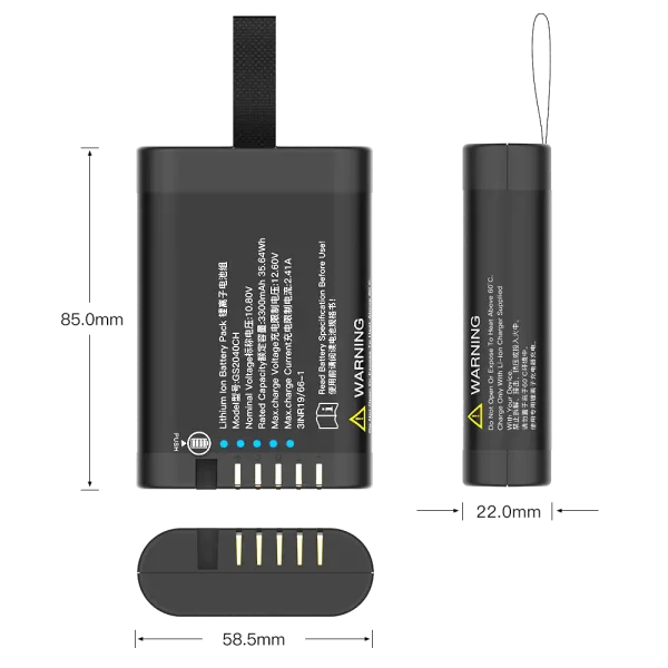
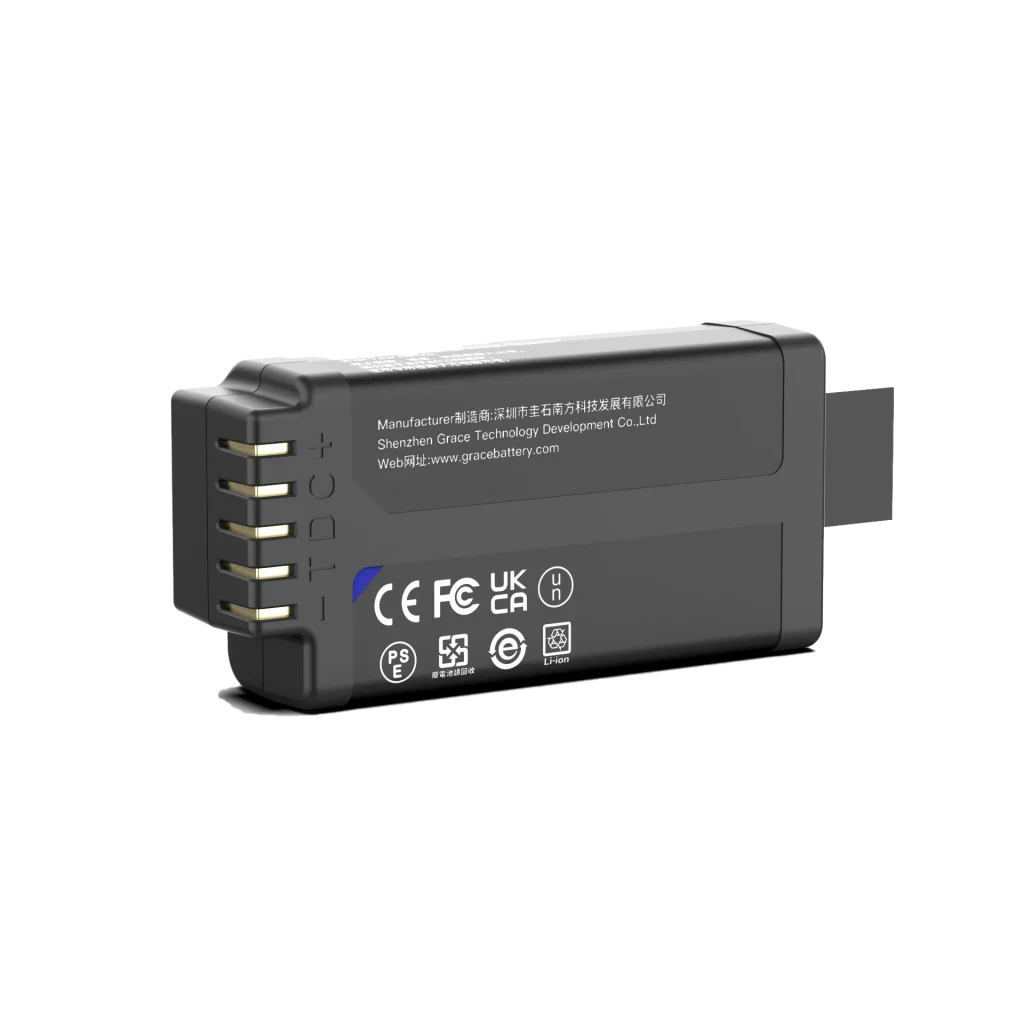
GS2040CH
10.8V/3450mAh/35.64Wh
2. Choose primary or rechargeable cells from the service model
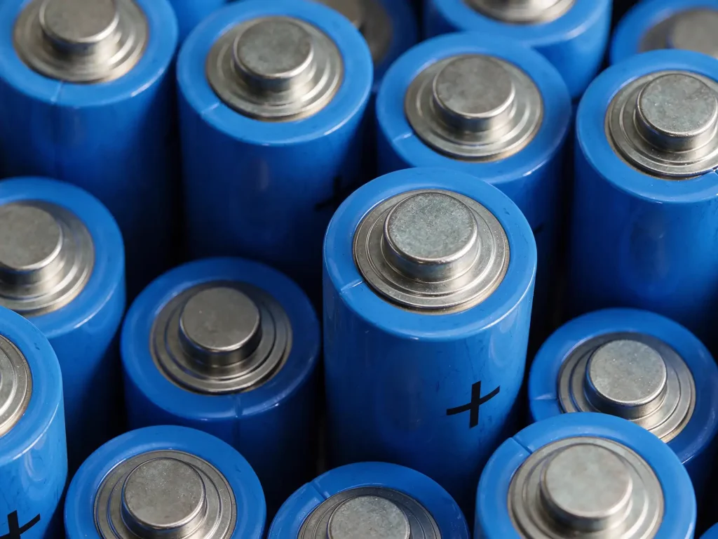
The right chemistry depends on whether the system is serviced, recharged, or expected to operate unattended. A primary lithium cell may suit a long-life, low-average-current node when recharge is unavailable, but pulse performance, passivation behavior, operating temperature, and the manufacturer’s permitted load profile need review. A rechargeable lithium-ion or lithium iron phosphate pack can suit maintained equipment or energy-harvesting systems, but it adds charging control, cycle-life, storage, and protection requirements. Neither category is universally best.
| Architecture | Potential fit | Design checks |
| Primary lithium | Remote nodes with planned replacement or no charging infrastructure | Pulse load limits, passivation recovery, storage temperature, shelf life, shipping classification. |
| Rechargeable Li-ion | Higher energy in a compact enclosure with a defined recharge plan | Charge temperature limits, pack protection, cycle and calendar life, charger compatibility. |
| Rechargeable LiFePO4 | Applications valuing cycle life and thermal stability where size and mass allow | Voltage window, low-temperature charging restrictions, energy density, balancing strategy. |
| Hybrid / harvested | Nodes with solar, vibration, or other intermittent energy input | Worst-season energy balance, storage buffer, charge control, and no-harvest fallback mode. |
For a rechargeable pack, select series count from the system voltage and regulator requirements. Select parallel count from usable energy and pulse capability, then verify current sharing, cell matching, interconnect resistance, and fault protection. For a primary cell, confirm that the manufacturer supports the measured pulse profile; a capacitor or pulse buffer may help, but it must be sized and validated for the radio waveform and recharge interval.
3. Validate peak current and voltage sag
Radio transmit pulses can pull the cell voltage below the node’s brownout threshold even when substantial capacity remains. A useful screening relationship is ΔV ≈ I_pulse × R_total, where R_total includes cell impedance at the relevant state of charge and temperature, tabs or welds, protection FETs, wiring, and connectors. Use a transient oscilloscope capture at the pack and load, then repeat at low state of charge, minimum operating temperature, and an aged-cell condition supported by the product requirements.
Check the full power path: radio module limits, regulator transient response, input capacitance, capacitor ESR, PCB return path, cable length, and connector resistance. A larger capacitor does not automatically fix the problem; it may mask an undersized cell, delay a power fault, or introduce unacceptable recharge peaks. The pass condition should be stated as a minimum supply voltage at the node during the worst credible pulse, with margin to the device’s reset threshold.
4. Define protection, telemetry, and firmware behavior
A rechargeable battery management system (BMS) commonly monitors cell voltage and temperature and protects against conditions such as overcharge, over-discharge, overcurrent, and short circuit. The required implementation depends on pack architecture and applicable product standards. For small wireless nodes, protection quiescent current matters: its drain can materially shorten life if it is not included in the energy budget. Primary-cell designs have different constraints and should not be described as BMS-protected unless the actual circuit provides those functions.
Define how firmware responds before a protection event: reduce radio transmit power or reporting frequency when the application permits, defer noncritical sensing, report a low-battery state, and preserve enough reserve for an orderly shutdown or final health message. Verify behavior during communication loss and at end of discharge. Telemetry such as pack voltage, temperature, reset reason, and estimated state of charge can support maintenance, but the estimate should be calibrated against the selected cell and load profile.
5. Design the enclosure and environment with the pack
Wireless sensor packs may face condensation, dust, vibration, impact, UV exposure, salt, or corrosive process gases. The battery enclosure and cable entry need to meet the system’s actual ingress and chemical exposure requirements without trapping unacceptable heat. Avoid transferring enclosure stress to cell seals, tabs, or welds. Define clearances for swelling where applicable, insulation barriers, strain relief, venting or pressure management, and a replacement method that prevents reverse polarity or incorrect cell substitution.
A sealed enclosure can complicate heat rejection and serviceability. Validate the assembly at the maximum ambient temperature, worst radio duty cycle, and relevant charge condition. If the device is outdoor-rated, include realistic temperature transitions and condensation in qualification planning; a static room-temperature capacity test does not establish outdoor life.
6. Build a verification plan before design freeze
| Level | Representative checks | Evidence to retain |
| Cell / source | Capacity and impedance sampling, lot traceability, pulse profile review | Approved cell specification, supplier change notice, incoming inspection plan. |
| Pack | Protection, pulse sag, temperature rise, insulation, vibration and drop as applicable | Configuration-controlled test report with limits, setup, and results. |
| System | Real firmware duty cycle, weak-link radio case, brownout, reporting and shutdown | Waveforms, runtime data, reset logs, and firmware / hardware revisions. |
| Field / transport | Temperature cycling, storage, service interval, shipping and market requirements | Qualification record, labeling, traceability, transport and compliance documents. |
Plan tests around the stated service-life target and environmental envelope. Use representative network conditions, and report the firmware configuration, reporting interval, transmit power, sensor set, temperature, and cell lot with any runtime result. For transport and product safety, determine applicable requirements from the destination market, battery configuration, and equipment category. UN Manual of Tests and Criteria subsection 38.3 addresses lithium battery transport testing; it is not a substitute for product safety certification. Standards such as IEC 62133-2, IEC 62619, or UL 2054 may be relevant depending on product type and market. Confirm current editions and applicability with the compliance body for the project.
7. Supplier questions for a custom battery pack
- Which cell manufacturer, model, chemistry, production site, and change-control process will be used?
- What continuous and pulse loads are supported at minimum temperature and end of service life?
- What are the pack voltage limits, impedance limits, protection thresholds, and quiescent current?
- How are lot traceability, incoming inspection, end-of-line testing, and field failure analysis handled?
- Which mechanical, ingress, vibration, drop, transport, and product-safety tests apply to the finished device?
- What evidence supports the quoted runtime, and under which firmware, radio, sensor, and temperature conditions?
Treat a runtime number as a test result with conditions, not as a property of capacity alone. Ask for raw or summarized discharge data and the test configuration, and agree on the acceptance method before production release.
Key engineering takeaway
A dependable custom battery pack for wireless sensor systems starts with a measured duty cycle and ends with a system-level validation that reproduces the real sensing and radio workload. Size usable energy for the intended service interval, separately prove pulse performance at cold and aged conditions, and include protection, firmware, enclosure, supplier controls, and compliance in the same design review. That process turns a capacity estimate into an evidence-based battery subsystem.
Frequently asked questions
How do I estimate battery life for a wireless sensor node?
Measure current and duration for every operating state, multiply each by its daily frequency, and sum the charge. Then account for usable discharge range, conversion losses, temperature, aging, self-discharge, and uncertainty. Validate the result with the production firmware and representative network conditions.
Why does a wireless sensor reset while the battery still appears charged?
A transmit pulse can cause voltage sag across the cell and power path, triggering brownout before the stored energy is exhausted. Check the waveform at the node during transmit, including low temperature, low state of charge, and interconnect resistance.
Should I use primary lithium or a rechargeable battery pack?
Choose from the maintenance and energy model. Primary cells can fit unattended deployments without charging; rechargeable packs can fit maintained or energy-harvesting systems. Verify the selected cell’s pulse, temperature, storage, and safety limits against the actual use case.
Does every custom battery pack need a BMS?
No universal answer applies. Rechargeable multi-cell packs commonly require cell monitoring and protection appropriate to their design. Primary-cell systems use different controls. Determine the required safeguards from the architecture, product risks, and target-market requirements.
What should a supplier provide before production approval?
Request controlled cell and pack specifications, pulse and temperature data, protection behavior, traceability and change controls, configuration-specific test reports, and evidence for applicable transport and product requirements.
References and technical basis
- IEC 62133-2, Safety requirements for portable sealed secondary lithium cells and batteries; check the edition applicable to the destination market.
- IEC 62619, Safety requirements for secondary lithium cells and batteries for industrial applications; confirm scope for the product.
- UL 2054, Household and Commercial Batteries; applicability depends on the product and market.
- United Nations Manual of Tests and Criteria, subsection 38.3, lithium battery transport testing.
- Selected cell manufacturer’s controlled datasheet and application guidance for pulse loads, temperature limits, storage, and charging.