Power budgeting, cell selection, BMS integration, thermal design and qualification
Technical blog | Updated November 2026
Executive summary
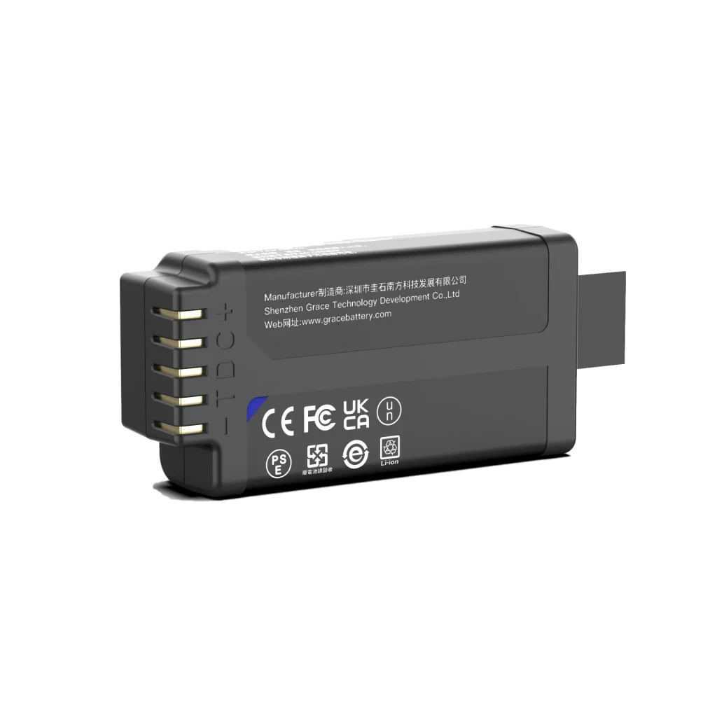
A battery pack for portable edge computers must deliver usable energy, stable peak power and predictable shutdown behavior within a compact enclosure. The best starting point is a measured system load profile. Use it to size energy and current separately, then coordinate the cell configuration, battery management system (BMS), thermal path, mechanical design and qualification plan.
This guide is intended for hardware engineers, product managers and sourcing teams developing industrial handheld computers, mobile vision systems, field AI devices and robotic edge nodes. Its central recommendation is straightforward: validate the complete battery subsystem under cold, aged and dynamic-load conditions before freezing the design.
1 Why portable edge computers need an application specific pack
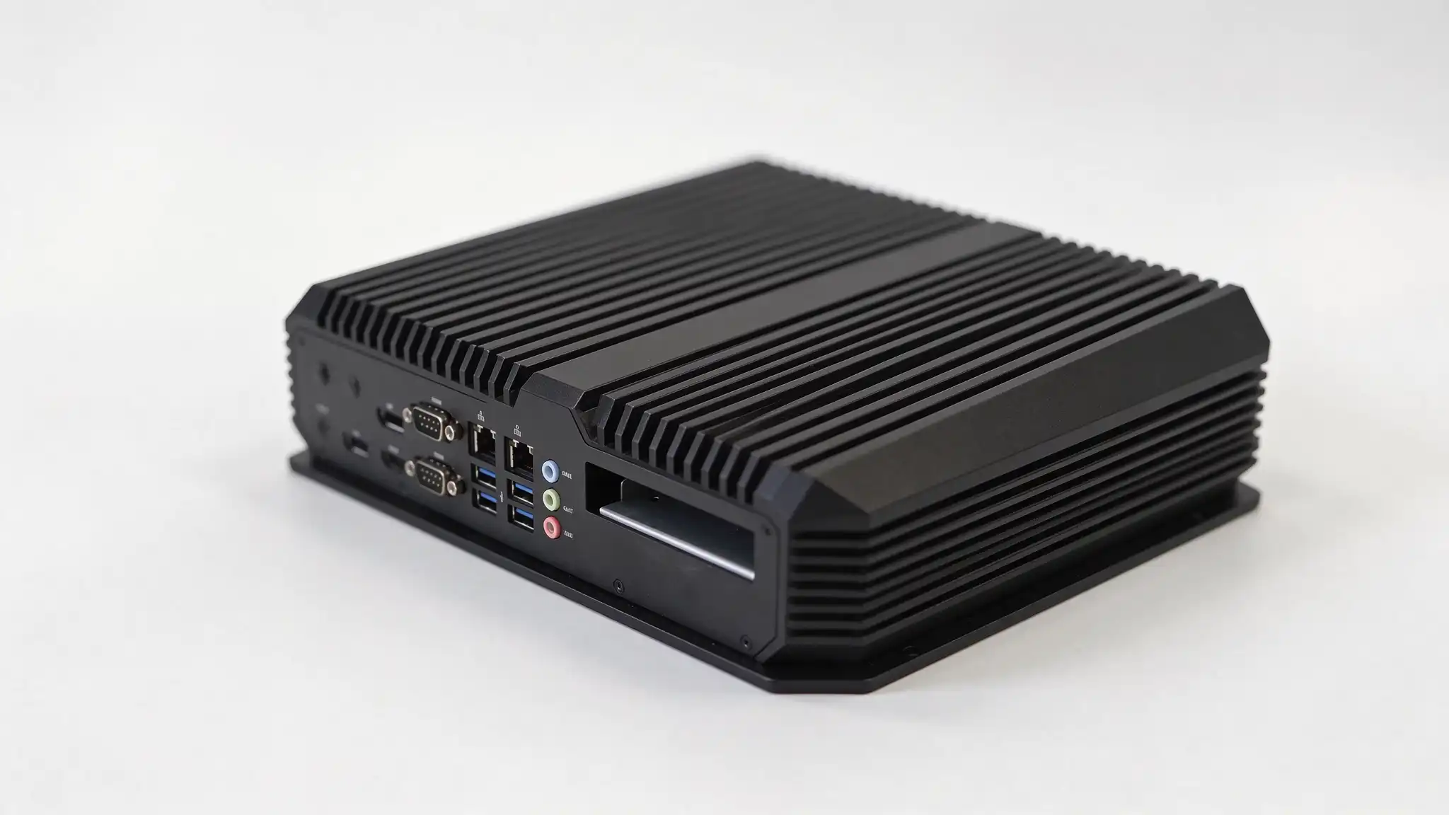
Portable edge computers often combine a CPU or GPU, an AI accelerator, high-speed storage, wireless communications and displays or sensor interfaces. Power consumption can change rapidly as the device moves from standby to inference, video encoding or data transmission. A pack that supports the average load may still allow a reset during startup or a short compute burst.
The battery subsystem therefore needs to meet five linked requirements:
- Provide enough usable energy across the operating temperature range and the host voltage window.
- Support startup, inference and radio peaks without excessive voltage sag or nuisance protection trips.
- Control heat in cells, interconnects, protection MOSFETs and connectors.
- Give the host enough status information and reserve energy for orderly shutdown and data protection.
- Fit the enclosure and meet the applicable transport and product safety requirements.
2 Define the power budget before choosing capacity
Measure at least standby, light computing, sustained inference, wireless transmission, maximum display brightness, cold startup and fault recovery. For each state, record pack voltage, current, duration and event frequency. Capture short peaks with enough bandwidth to resolve them. Use a representative prototype and a calibrated measurement setup.
For a first estimate, nominal pack energy can be screened with:
E_nominal >= (P_average x t_target) / (eta x DOD x k_temperature x k_aging)
P_average is the time-weighted load power, t_target is required runtime, eta is the average conversion efficiency, and DOD is the allowed depth of discharge. The temperature and aging factors represent retained usable capacity under the design conditions. Use consistent energy boundaries, count BMS and standby losses, and avoid counting the same derating twice. Replace these screening factors with measured pack discharge data before release.
Illustrative calculation: a 35 W average load running for 3 hours needs 105 Wh at the load. With eta = 0.92, DOD = 0.90, k_temperature = 0.90 and k_aging = 0.80, the initial estimate is about 176 Wh nominal. These are calculation assumptions, not measured performance or a recommended pack specification.
Check peak current separately. If the pack must deliver 180 W at its terminals at a minimum operating voltage of 12 V, current is 15 A. If 180 W instead describes the load after a converter, include converter losses. Verify cold and aged voltage sag across the cells, protection circuit, wiring and connectors, as well as the duration allowed by every component.
3 Select cell chemistry and series parallel configuration
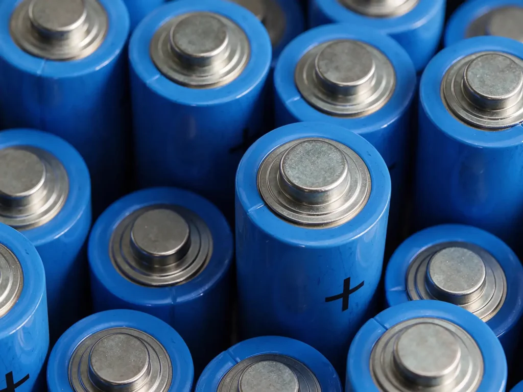
Cell chemistry and cell format are separate decisions. Common rechargeable choices include nickel-based lithium-ion chemistries such as NMC and NCA, and lithium iron phosphate (LFP). Cylindrical, prismatic and pouch cells can be available in different chemistries. Compare the actual cell models against the same energy, current, temperature and life requirements.
| Choice | Potential advantage | Engineering constraint | Typical fit |
| NMC or NCA | Relatively high specific energy for weight-sensitive equipment. | Thermal, charging and abuse limits require careful control. | Mobile vision and compact field AI devices. |
| LFP | Often attractive for cycle life and thermal stability. | Typically more mass or volume for equal energy; verify cold performance. | Industrial devices where size and mass allow. |
| High power cell model | Lower impedance and stronger pulse capability, depending on the model. | May trade energy density for power; chemistry and format still matter. | Frequent compute bursts or high startup loads. |
Choose the series count from the full host input-voltage window, including maximum charge voltage and minimum voltage under load. Choose the parallel count from both usable energy and worst-case current. Check the charger and converter across that entire range, rather than matching only nominal voltages.
Confirm continuous and pulse ratings, allowed pulse duration, charge current, temperature-dependent limits and cell matching requirements. Control capacity and impedance variation between cells and lots. Increasing ampere-hours alone does not solve a weak power path or an unsuitable protection strategy.
4 Make the BMS part of the host power strategy
Overcharge, over-discharge, overcurrent, short-circuit and temperature protection are essential design considerations, with the implementation determined by the cell, pack architecture and product requirements. For a portable edge computer, the BMS should also support energy estimation, useful telemetry and fault diagnosis.
| Function | Design focus | Useful host data |
| State estimation | Calibrate coulomb counting with cell behavior, temperature and aging. | SOC, SOH and estimated remaining runtime. |
| Power limits | Derate with temperature, voltage, SOC and current where supported. | Allowed charge and discharge current or power. |
| Protection | Coordinate thresholds, delays, latching and recovery with the host. | Fault codes, protection state and recovery reason. |
| Communication | Define data units, update rates, timeout behavior and version control. | CAN, SMBus or UART messages as appropriate. |
| Event history | Retain useful extremes and counters within memory constraints. | Temperature and current peaks, cycles and fault records. |
State of charge (SOC) estimates remaining charge; state of health (SOH) describes degradation against a defined reference. Remaining runtime depends on the load forecast as well as the battery estimate. Treat it as an estimate and validate it with representative workloads.
Protection thresholds should not become normal operating targets. Set earlier host warning points so software can reduce compute power, dim the display, defer noncritical inference or shut down cleanly. Test communication loss and unexpected load changes. A hardware protection cutoff remains necessary even when software normally manages the limit.
5 Design thermal paths and mechanical integration together
The cells are only part of the thermal problem. DC-DC converters, protection MOSFETs, connectors and processors can create adjacent hot spots in a small enclosure. Insulating foam used for vibration control can also trap heat. Define the intended heat path to the enclosure or cooling structure, then verify it under simultaneous compute and charging loads where those conditions are allowed.
Provide electrical insulation, mechanical clearances, swelling allowance where applicable and an appropriate venting or pressure-management strategy. Do not create a thermal interface that compromises cell insulation or transfers enclosure loads into cell terminals.
- During drop, vibration and torsion tests, keep damaging stress away from cell tabs, seals and welds.
- Validate connector retention, contact resistance, mating cycles and cable strain relief.
- Account for cell dimensional changes, housing tolerances and assembly compression.
- Route supply and return paths to limit noise near antennas, cameras and high-speed interfaces.
Measure bus ripple, transient response and ground disturbance during radio transmission while checking camera and compute stability. Address electromagnetic compatibility (EMC) during prototype integration, because a late filter or cable change can alter voltage drop, heat and transient behavior.
6 Validate the cell the pack and the complete device
A production qualification plan should connect cell-level evidence to pack-level and system-level results. Define pass criteria before testing, including the load profile, ambient temperature, SOC, aging condition, firmware version and sample configuration. The table below is a planning framework; the test severity and sample plan must match the product requirements.
| Level | Representative checks | Evidence to retain |
| Cell | Capacity, impedance, rate capability, cold behavior, cycling and relevant safety evidence. | Controlled datasheet, approved cell model and incoming inspection limits. |
| Pack | Protection behavior, short circuit, temperature rise, insulation, drop and vibration as applicable. | Configuration-specific reports, protection settings and failure records. |
| System | Dynamic loads, cold startup, host derating, shutdown and communication loss. | Waveforms, runtime data, firmware revision and fault-response results. |
| Transport and market | Applicable lithium transport tests and product safety assessment. | Test reports or summaries, labels, shipping documents and traceability. |
Common safety references include IEC 62133-2 for portable sealed secondary lithium cells and batteries, IEC 62619 for industrial secondary lithium applications, and UL 2054 for household and commercial batteries. Applicability depends on the equipment, market and certification route. These standards are not interchangeable, and a tested cell does not automatically qualify the finished pack or device. [1-3]
UN Manual of Tests and Criteria subsection 38.3 addresses lithium battery transport testing. Passing the applicable tests does not by itself satisfy all packaging, labeling, documentation or carriage requirements, and it does not replace product safety evaluation. Confirm the rules for the specific shipment and destination. [4]
Request the report number, standard edition, test conditions and exact tested configuration. A generic certificate cover page cannot establish that the purchased configuration has the required evidence.
7 Use a clear supplier approval checklist
Before production approval, include the following items in the technical agreement and require documented supplier responses:
- Cell manufacturer, model, chemistry, lot traceability and matching or grading rules.
- Rated and minimum capacity, continuous and pulse current limits, and temperature derating data.
- BMS hardware and firmware revisions, protection settings, protocol and fault-code definitions.
- Housing materials, applicable flammability and ingress requirements, connector and critical tolerances.
- Qualification sample plan, test conditions, acceptance criteria and corrective-action process.
- Production test coverage, retained shipment data, change control and field failure analysis.
Compare engineering and production samples for capacity, impedance, pulse voltage sag, temperature rise and communication behavior. Linking pack serial numbers to device serial numbers can improve field diagnosis and support targeted corrective action.
Engineering takeaway
Selecting a battery pack for portable edge computers requires energy, peak power, thermal behavior, host coordination and compliance to work within one system boundary. Start with the measured workload, select cells and architecture from explicit limits, then validate the assembled subsystem under representative conditions. This turns a capacity estimate into an engineering basis for a repeatable production design.
Frequently asked questions
Is a larger battery pack always better for a portable edge computer?
No. More energy can increase mass, volume, charging time and shipping constraints. Size usable energy for the required workload and runtime, then independently verify peak power, temperature and aging performance.
Why can an edge computer shut down while charge remains?
A current peak can cause voltage sag that triggers host undervoltage or pack protection. Higher cell impedance, low temperature, connector resistance or a BMS power limit can contribute. Examine voltage and current waveforms together with temperature and fault logs.
How can a buyer judge whether a pack is ready for production?
Review cell consistency, controlled BMS firmware, configuration-specific test evidence, production testing, traceability and change control. Sample capacity alone does not establish production readiness.
References and technical basis
[1] IEC 62133-2. Safety requirements for portable sealed secondary lithium cells and batteries. Confirm the applicable edition and amendments for the destination market.
[2] IEC 62619. Safety requirements for secondary lithium cells and batteries for industrial applications. Confirm whether the product falls within scope.
[3] UL 2054. Household and Commercial Batteries. Applicability depends on the product and market.
[4] United Nations. Manual of Tests and Criteria, Part III, subsection 38.3. Consult the applicable revision and transport rules.
Calculations and design recommendations in this article are engineering screening guidance. Final ratings, limits and runtime claims should be based on the selected cell documentation and representative pack and system tests.