How 7.2V SMBus battery packs are specified, monitored, protected, and validated
Article
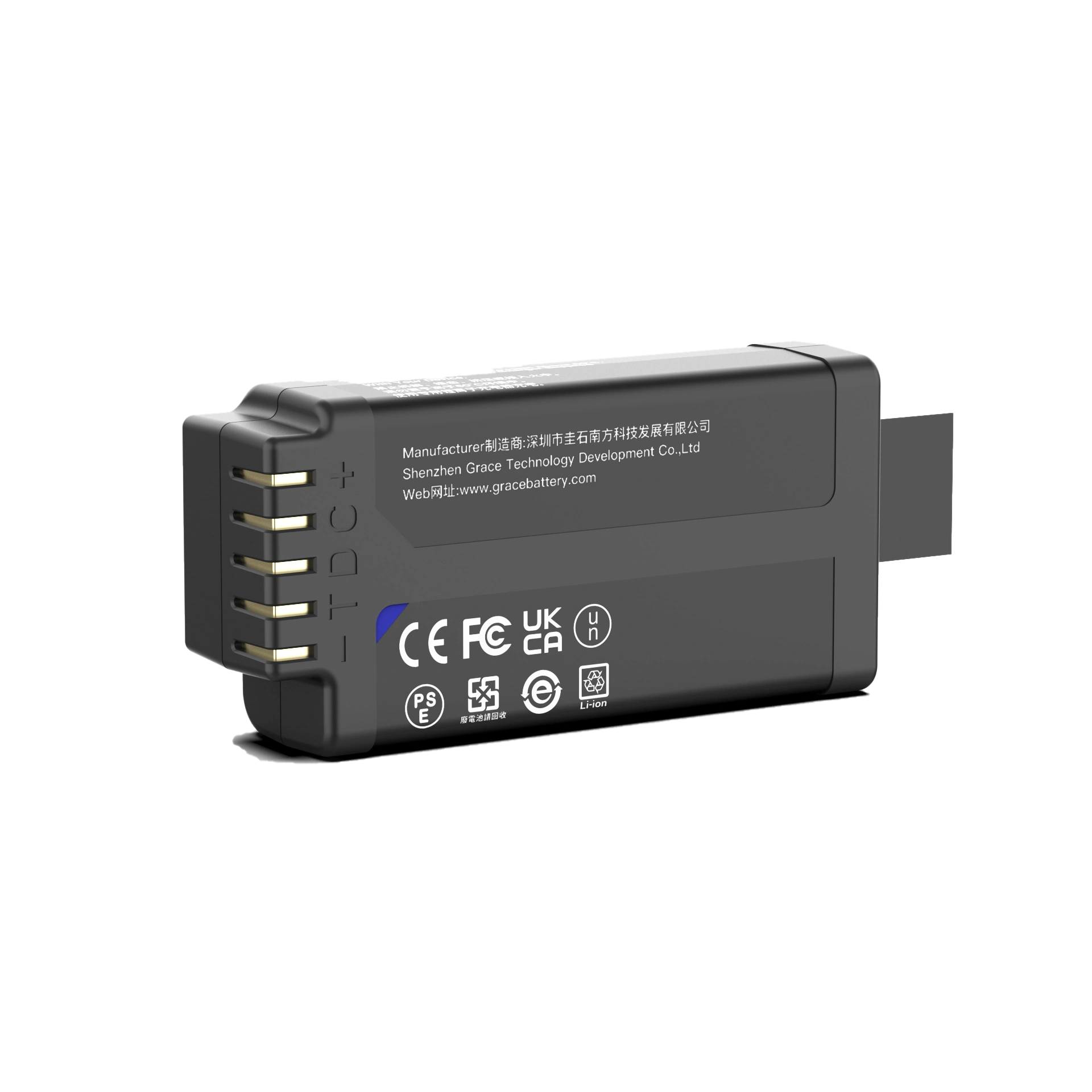
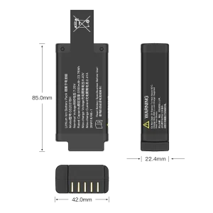
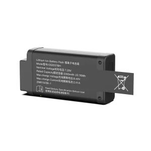
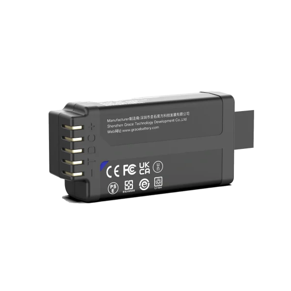
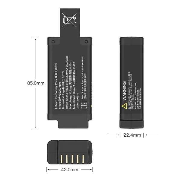
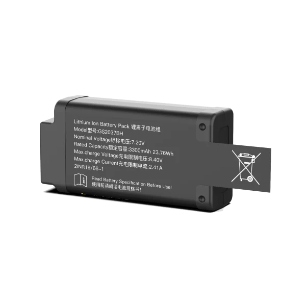
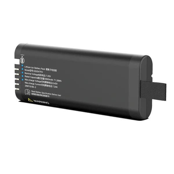
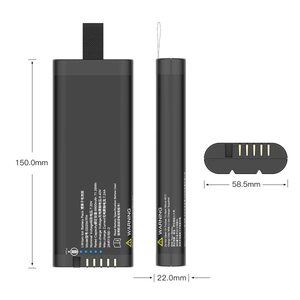
A 7.2V 2S1P lithium ion battery pack combines two cells in series and one cell in each parallel position. That topology sets the pack’s voltage class, but it does not by itself define usable capacity, charge voltage, current capability, protection, or communications. A 7.2V SMBus battery pack adds a digital interface for reporting battery data to a host; it still needs a correctly configured fuel gauge, protection circuitry, and system-level validation. Selecting the pack therefore starts with the host’s full electrical and operational requirements, not the label alone.
What 2S1P means in practice
In a 2S1P arrangement, two single-cell groups are connected in series. Series connection adds voltage while the ampere-hour capacity remains approximately that of one cell. If each cell is rated at 3.6V nominal and 2.5Ah, the example pack is nominally 7.2V and 2.5Ah, or about 18Wh before accounting for conversion losses and operating limits. A different cell with a 3.7V nominal rating would produce a 7.4V nominal pack. Vendors sometimes use 7.2V and 7.4V to describe similar two-cell voltage classes, so confirm the actual cell specification.
The maximum charge voltage is chemistry- and cell-specific. For cells whose approved charge limit is 4.2V, a two-cell series pack reaches 8.4V at the specified full-charge condition. Other lithium-ion chemistries use different limits. Never infer charge voltage from the 7.2V label; use the cell manufacturer’s data sheet and the pack’s approved charge profile.
| Pack attribute | What 2S1P tells you | What still needs specification |
| Topology | Two series cells, one parallel path | Cell model, interconnect and mechanical arrangement |
| Nominal voltage | About twice the selected cell’s nominal voltage | Cell chemistry and exact voltage range |
| Capacity | Approximately one cell’s Ah rating | Rated and minimum capacity under stated conditions |
| Energy | Nominal voltage multiplied by Ah capacity | Usable energy after cutoff, temperature and load effects |
| Charge and current | Not fixed by topology | Approved charge limits, continuous and pulse loads, thermal limits |
When an SMBus interface is useful
SMBus (System Management Bus) is a two-wire, host-managed serial bus commonly used for system monitoring and power-management communication. Smart Battery specifications define a set of battery-related data and commands that a compatible host can use to read information such as voltage, current, temperature, state of charge, remaining capacity, and status flags. Exact fields, units, access behavior, and supported commands depend on the implementation and the applicable specification revision.
A 7.2V SMBus battery pack can help a device estimate runtime, show a low-battery warning, record battery health, and make controlled shutdown decisions. The host must still interpret returned values correctly and handle missing, stale, out-of-range, or unsupported data. SMBus telemetry is not a substitute for hardware protection: the pack must independently prevent unsafe operating conditions even if the host is asleep, disconnected, or has a software fault.
Core design elements
Cell selection and series matching
Choose cells for the actual load profile, temperature range, lifetime target, and enclosure. Check energy and power requirements separately: a design with adequate watt-hours can still fail if cell impedance or protection thresholds cause excessive voltage sag during a current pulse. In a series string, cell capacity, impedance, self-discharge, and aging differences can lead to imbalance. The design should define cell sourcing controls, incoming inspection, balance strategy where applicable, and end-of-line checks.
Fuel gauge, protector, and switching path
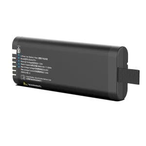
The fuel gauge estimates charge and reports data; the protector enforces electrical limits; charge and discharge FETs control the current path. These functions may be integrated or distributed, but their roles must be explicitly assigned. Gauge configuration needs to match the selected cell chemistry and pack design, including capacity assumptions, current-sense scaling, temperature sensing, and voltage thresholds. Confirm that a protection response does not conflict with the host’s normal load transients or the charger behavior.
Temperature sensing and secondary safety
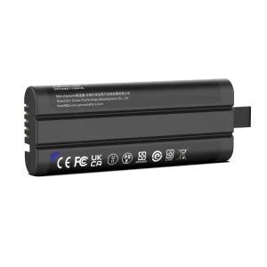
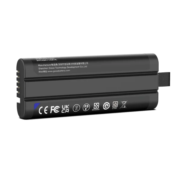
Place the thermistor where it can represent the cell temperature relevant to charge and discharge decisions, and validate its readings under realistic thermal gradients. A fuse or other secondary protective element may be required by the risk analysis and applicable product requirements. The pack design should address short circuit, overcurrent, overcharge, overdischarge, abnormal temperature, wiring faults, and foreseeable misuse. Required tests and certifications depend on the end product, market, and shipping route; they should be identified with qualified compliance specialists early in development.
SMBus integration checklist
- Confirm bus voltage levels, pull-up ownership, connector pinout, ground reference, and host electrical limits.
- Agree on the supported Smart Battery commands, units, scaling, update intervals, and error behavior.
- Verify addressing and bus timing against both host and pack documentation; account for clock stretching and bus recovery where supported.
- Test pack insertion, removal, brownout, host reset, low state of charge, sensor faults, and communication timeouts.
- Compare reported voltage, current, temperature, and capacity with calibrated external instruments across the operating range.
- Keep protection independent of firmware and test that telemetry failures cannot disable protective hardware.
Validation before release
A production-ready 7.2V 2S1P lithium ion battery pack should be validated as a pack and as part of the host system. At minimum, define acceptance limits for capacity and energy, charge and discharge behavior, protection trip and recovery, cell balance, temperature sensing, SMBus interoperability, idle consumption, and mechanical fit. Run tests at relevant temperatures and load profiles, and repeat communication checks during power transitions and fault conditions. Record firmware and gauge configuration revisions with the test data so results can be traced to the shipped design.
For an SMBus pack, a useful release criterion is not simply “the host can read state of charge.” Confirm that the host’s decisions remain safe when the reported estimate is inaccurate or unavailable, and that protective cutoffs operate correctly without host cooperation. Validate the intended charger and host together; compatibility cannot be established from nominal voltage alone.
How to specify a 7.2V SMBus battery pack
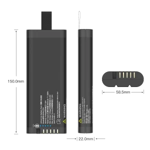
A supplier request should state the host’s input-voltage window, required capacity or runtime, continuous and peak current, charging method, enclosure limits, operating and storage temperatures, connector and pinout, required SMBus command set, and expected service life. Also identify the target markets and product standards, desired traceability, sample and production quantities, and validation evidence required. Ask the supplier to disclose the cell model, pack voltage limits, protection thresholds, gauge configuration process, and test coverage. These details make proposals comparable and expose integration risks before tooling or qualification begins.
Frequently asked questions
Is a 7.2V 2S1P battery always 8.4V when fully charged?
No. 8.4V applies to a two-cell series pack only when the selected cells have an approved 4.2V maximum charge voltage. Confirm the exact chemistry and cell data sheet before setting charger limits.
Does SMBus mean the pack is a smart battery?
SMBus describes a communication bus. A compatible smart battery implementation also needs defined battery data and commands, a suitable gauge and firmware configuration, and a host that supports the chosen behavior.
Does 2S1P determine battery capacity?
No. The P count indicates one cell in each parallel group, so pack ampere-hour capacity is approximately the capacity of the selected cell. The cell rating and test conditions determine the actual value.
Can any 7.2V charger charge this pack?
No. Charger compatibility depends on the cell charge profile, pack voltage limits, current limits, temperature controls, and system design. Use a charger approved for the exact pack configuration.
Engineering conclusion
A dependable 7.2V 2S1P lithium ion battery pack is defined by its cells, voltage limits, current capability, protective design, thermal behavior, and verified fit with the host. Adding SMBus can make battery state visible to the system, but it does not remove the need for independent hardware protection or disciplined charger validation. Treat voltage, capacity, command support, and safety behavior as separate requirements that must be tested together.
For procurement and qualification, specify the cell model and chemistry, the full operating voltage range, load and runtime targets, charging conditions, environmental limits, SMBus data requirements, and evidence expected from validation. That level of detail helps engineering teams compare pack proposals on measurable behavior and gives the supplier a clear basis for a safe, interoperable design.
Engineering references
The interface and fuel-gauge behavior should be implemented against the applicable specifications and component documentation. These primary references are useful starting points; confirm the revision that applies to the product: