-260719-4-edited.png)

The lithium battery pack is already integrated a safety protection circuit to prevent accidents and ensure safe use of the battery. However, the battery pack does not contain a charging circuit. If you need to charge the battery inside the device, the host must have a charging management circuit and path management circuit. TEFOO recommends the following charging process to ensure the best performance of the lithium battery pack.
I. Charging method
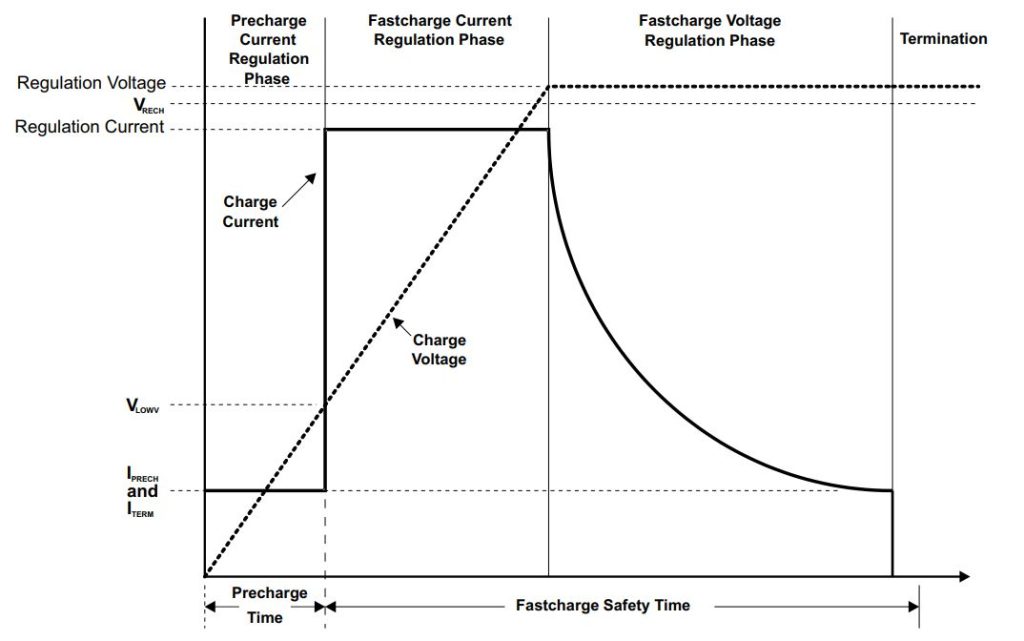
Lithium batteries require a constant current and constant voltage (CC/CV) charging method. The typical charging voltage and charging current curves are as follows:
II. Functions and performance required for charging
1. Charging voltage
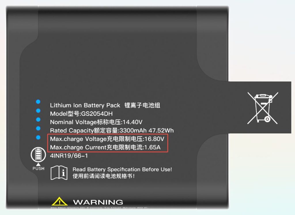
The charging voltage of a lithium-ion battery pack must not exceed the battery pack’s charge limit voltage. Generally, the battery pack’s charge limit voltage = N * 4.2V (N is the number of cells in series). For example, the charge limit voltage for a three-cell lithium-ion battery pack is 12.6V. If you desire improved battery cycle life, you can lower the charge voltage to N * 4.15V. Below this value, the lithium-ion battery pack will not fully charge. Considering the potential for errors in the charging chip and peripheral circuitry, TEFOO recommends that the charging circuit’s charge voltage accuracy error not exceed 0.5%. Otherwise, the battery may fail to fully charge.
2. Charging current
The charging current of a lithium-ion battery pack must not exceed the battery pack’s charge limit. A charge current lower than the actual design limit is permitted, but the lower the charge current, the longer the charge time.
3. Charging temperature
The allowable charging temperature range for lithium battery packs is 0-50 ℃. If it exceeds this range, the battery pack will cut off the charging circuit and external circuits are prohibited from charging the battery. TEFOO suggests reducing the charging current to 0.3C within the temperature range of 0-10 ℃, and reducing the charging circuit to 0.2C and charging voltage to N * 4.15V within the temperature range of 45-50 ℃, in order to prolong the service life of the lithium battery pack.
4. Precharge
When the total voltage of the battery pack is lower than N * 3.0V, TEFOO suggests using a smaller charging current to activate the internal chemical reaction of the battery, precharge current usually is 0.1C-0.2C. When the total voltage of the battery pack is higher than N * 3.0V, it will turn to the standard charging current.
5. Full charge condition
There are two conditions for calculating whether the battery pack’s RSOC is 100%:
l The total voltage of the battery pack is greater than N * 4.125V;
l The charging current of the battery is less than the cut-off current of the battery and continued for more than 80 seconds;
After meeting these two conditions, RSOC will be converted to 100%. So the cut-off current of the charging circuit must be less than the termination current of the battery. TEFOO suggests that the charging cut-off current approximately equal to battery termination current -50mA.
6. Safe charging time
To ensure that the battery is not severely overcharged in case of abnormalities and further improve the safe use of lithium batteries, TEFOO suggests setting a safe charging time protection for the charging circuit, with a recommended charging time protection value of 1.5 times the time required for normal charging. If the battery still cannot be fully charged after this time, stop charging.
III. Charging circuit design
1. Switch-Mode Buck Charging
When the adapter supply voltage is higher than the battery voltage, for example, using a 19V adapter to power a device while simultaneously using a four-cell series lithium-ion battery pack, the adapter simultaneously charges the battery and powers the system. When the adapter is powered off, the battery seamlessly switches to powering the system. In this architecture:
When the adapter is powered on, the system supply voltage equals the adapter voltage.
When the adapter is powered off, the system supply voltage equals the battery pack voltage.
A typical example of this type of circuit is the BQ24610 from TI.
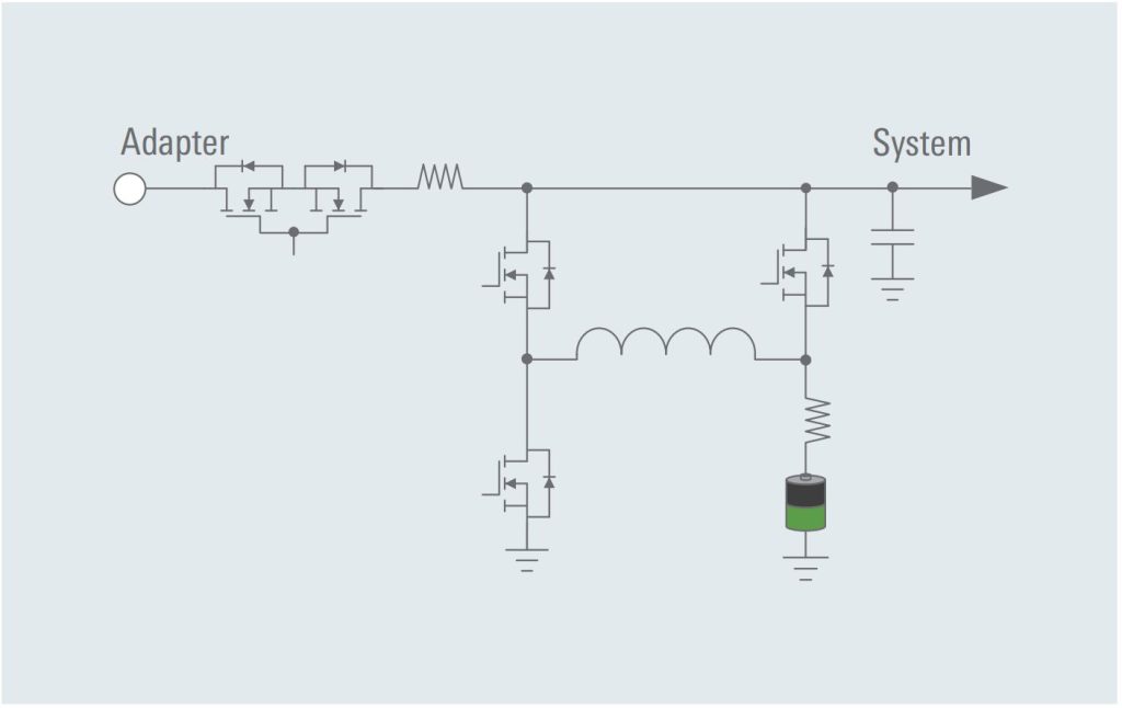
Switch-Mode Buck Charging block diagram
2. Switch-Mode Buck-boost Charging
When the input voltage is lower than the battery voltage or the system is powered by a different input power source, for example, using a 12V or 19V adapter to power a device while simultaneously using a four series lithium-ion battery pack, the system simultaneously charges the battery and powers the system when the adapter is powered. When the adapter is powered off, the battery seamlessly switches to powering the system.
In this architecture, the system supply voltage always equals the battery voltage.
A typical choice for this type of circuit is the BQ25710 from TI.
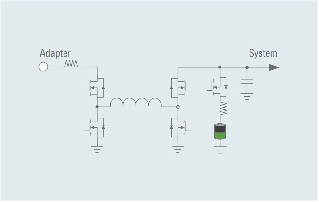
Switch-Mode Buck-Boost Charging block diagram
3. Charging using USB-C PD protocol
With the widespread use of USB-C interfaces, more and more portable devices use USB-C as the main power supply interface. Through the PD protocol, a PD decoy or microcontroller can be used to request a higher voltage (commonly 5V/9V/12V/15V/20V) from the PD adapter to power the system and battery.
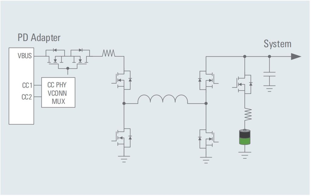
USB-C PD protocol charging block diagram
IV. Charging management board
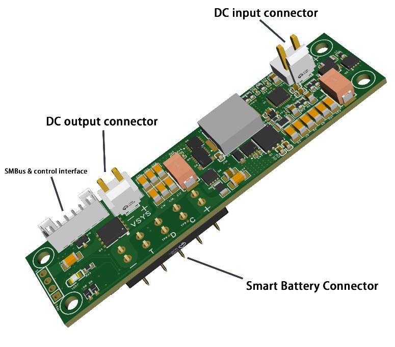
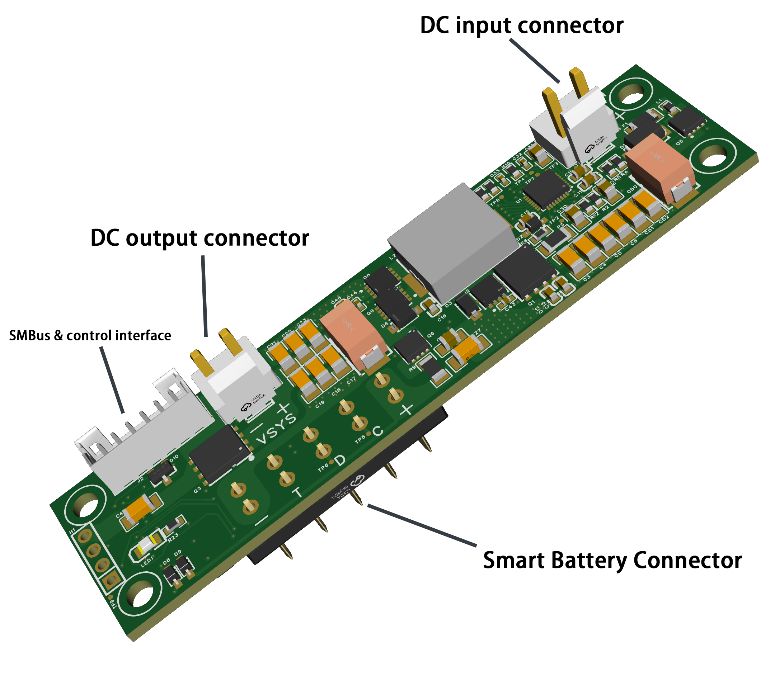
If you do not want to develop a charging management circuit for various reasons, TEFOO can provide two finished power management boards for direct selection.
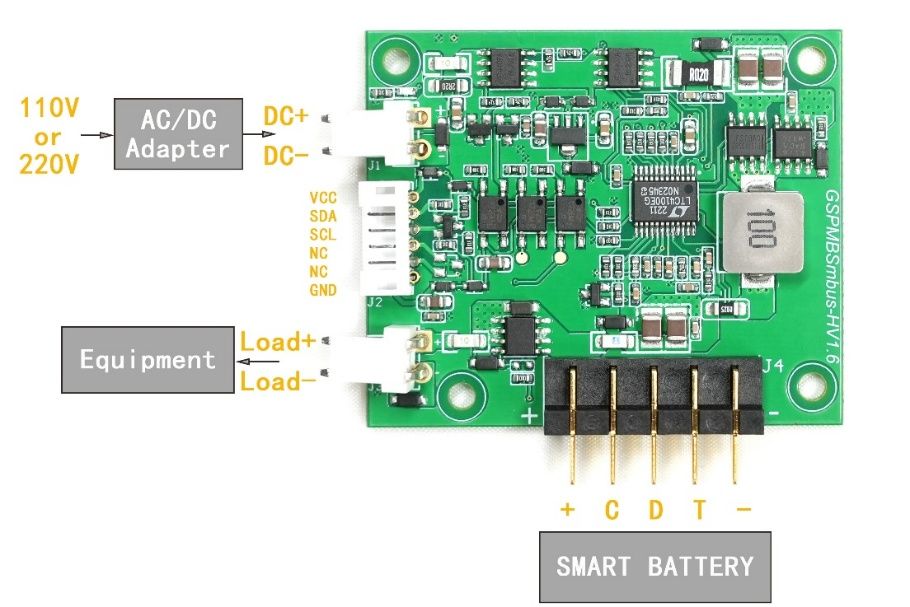
1. GSPMBSMBus
Features:
l Switch-Mode Buck Charging.
l compatible with all standard smart batteries with SMBus interface.
2. GSPMB20
Features:
l Switch-Mode Buck Charging.
l compatible with all standard smart batteries with SMBus interface.