Portable spirometer battery pack design starts with the device load
A portable spirometer battery pack must do more than provide enough milliamp-hours on a datasheet. It must keep the spirometer’s sensing, processing, display, alarms, and data-transfer functions within their specified operating limits throughout the intended use period. That requires a battery design based on the complete device load profile, the required runtime, the operating environment, and the applicable medical-device requirements.
For product teams, the most reliable sequence is to measure the real duty cycle, translate it into usable energy, check transient voltage under the worst credible load, then verify the finished device across temperature, aging, and end-of-discharge conditions. The equations below support early sizing; final capacity and service-life claims should come from the selected cell data and system-level testing.
Why the battery can affect spirometer performance
A spirometer may spend much of its time in standby and then draw brief peaks while its display wakes, sensors stabilize, a measurement is processed, or a wireless connection transmits results. Average current alone can miss these peaks. If the battery voltage falls below a regulator or processor threshold during an event, the device may reset, interrupt a session, lose stored data, or behave outside its specified performance limits.
The power budget should therefore include every subsystem active during a measurement: the flow or pressure sensing path, analog front end, processor, display, indicators, storage, and wired or wireless interfaces. Confirm the required voltage and noise limits with the spirometer electronics and sensor specifications. Battery selection does not establish measurement accuracy; the complete instrument must continue to meet its stated performance requirements on battery power.
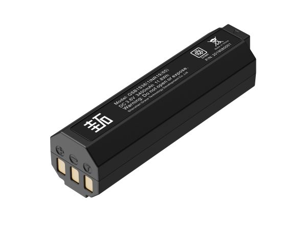
1. Measure the duty cycle before choosing capacity
Record current and duration for standby, startup, sensor warm-up or stabilization, measurement, processing, display use, data transfer, and charging if applicable. Measure at the battery terminals and at sensitive supply rails. Include realistic use patterns such as repeated measurements, screen brightness, wireless retries, low-battery operation, and any accessories powered by the device.
Daily energy (Wh) = sum of [load power (W) x time (hours) x events per day]
If starting from current, calculate charge for each operating state and account for its voltage. Convert to watt-hours when the supply voltage varies or when comparing cells with different nominal voltages. Estimate required nominal capacity only after allowing for regulator losses, the permitted discharge window, temperature, cell aging, self-discharge, protection-circuit consumption, and uncertainty in usage. Keep each assumption visible so it can be updated when the design or use profile changes.
| Operating state | What to measure | Why it matters |
| Standby | Settled current with all intended interfaces enabled | Small continuous loads accumulate over long idle periods. |
| Measurement | Sensor stabilization, acquisition time, and repeated tests | The sensing chain and processor may run at a different load than standby. |
| User interface | Display, backlight, indicators, and audio alerts | Brightness and interaction patterns can shift runtime materially. |
| Data transfer | Peak current, connection time, retries, and accessories | Short peaks can cause voltage droop even when average use is low. |
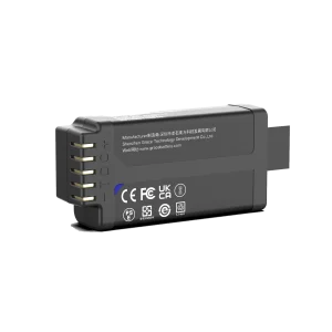
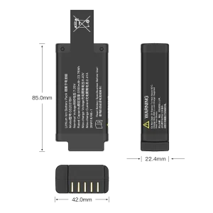
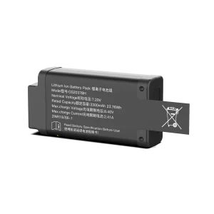
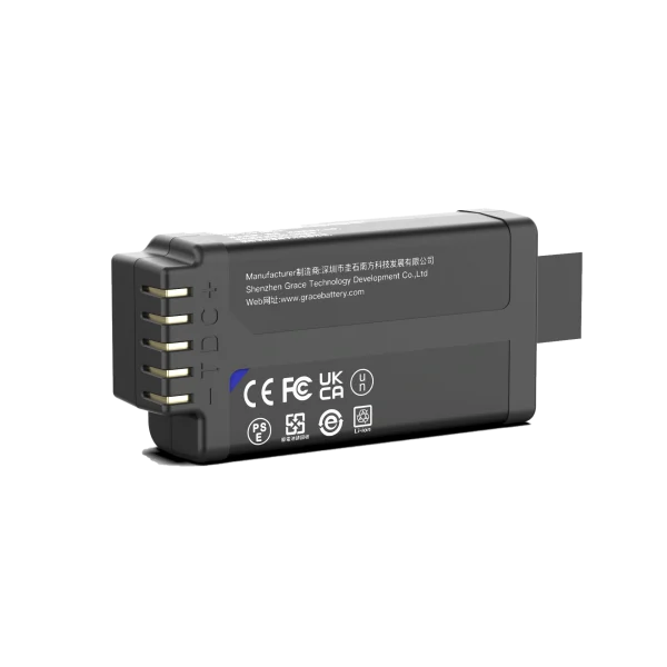
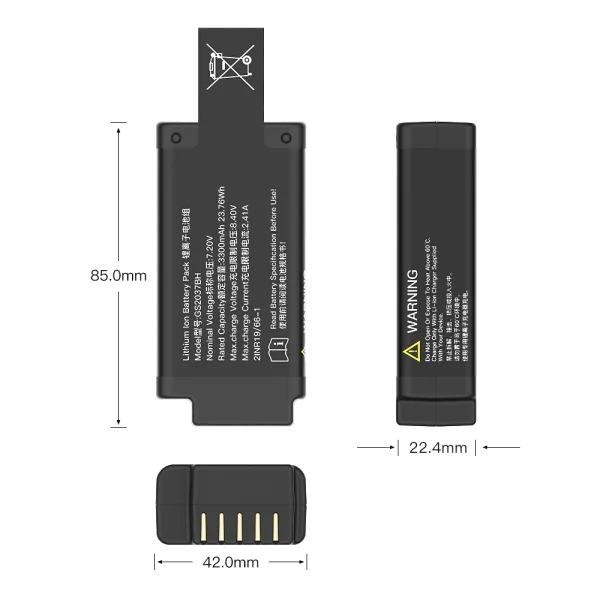
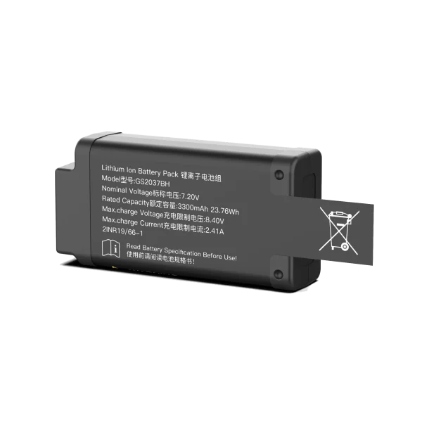
2. Select chemistry and pack architecture for the use model
Choose between replaceable primary cells and a rechargeable pack from the expected service model, runtime, enclosure, charging access, and market requirements. Primary cells can suit devices designed for periodic replacement, but their pulse capability, shelf life, voltage curve, and permitted operating conditions must match the load. Rechargeable lithium-ion packs can support frequent use and predictable charging workflows, while adding charge-control, cycle-life, storage, and protection requirements. No chemistry is the right choice for every spirometer.
The series configuration must fit the device’s input-voltage range and regulator design. Parallel capacity, when used, should be supported by cell data and a pack design that addresses current sharing, interconnect resistance, protection, and cell matching. Review the full discharge curve, not only nominal voltage and advertised capacity. Also check replacement access, connector polarity, mechanical retention, and whether users can install an incorrect cell type.
3. Check peak current and voltage sag
The cell and the complete power path have resistance. During a current pulse, the approximate voltage drop is ΔV = I x R, where total resistance includes cell impedance, interconnects, protection devices, wiring, and connectors. Validate the actual waveform at the battery and at critical system rails. Repeat near the lowest permitted state of charge and at the minimum operating temperature; aged-cell behavior should be included where it is part of the product requirement.
Check that the minimum rail voltage remains above the relevant reset and sensor limits with margin. Review regulator transient response, input capacitance, capacitor ESR, PCB layout, and radio or display peak loads together. A larger capacitor can help with a short transient, but it does not replace verification of cell capability or total runtime. Define the pass criterion in the product requirements and test it on production-representative hardware.
4. Design charging, protection, and low-battery behavior
A rechargeable pack needs a charging method matched to its chemistry, cell count, temperature limits, and intended charging interface. The protection design should address the faults relevant to the pack, such as overcharge, over-discharge, overcurrent, and short circuit. Its standby consumption belongs in the runtime budget. Confirm safe behavior for charging interruptions, connector faults, and storage at the specified conditions.
Firmware should give users a clear low-battery indication before the pack reaches its cutoff. Define the remaining reserve needed to complete or safely stop a measurement, preserve stored data, and communicate status. Test the warning threshold under representative loads because battery voltage can rebound after a pulse. A displayed state-of-charge estimate should be validated for the selected chemistry and load profile; open-circuit voltage alone may not provide a dependable estimate across the whole discharge curve.
5. Integrate the battery with cleaning and enclosure requirements
Portable medical equipment may be wiped, disinfected, carried between locations, or exposed to spills. Design the battery compartment, seals, connectors, and service access around the device’s labeled cleaning and environmental requirements. Avoid transferring enclosure stress to cell seals, tabs, or welds, and provide strain relief and insulation appropriate to the assembly. The battery and its materials must be compatible with the validated cleaning process and stated environment.
Verify heat rise during charging and during the device’s highest credible operating load. A sealed or compact enclosure changes heat rejection and may complicate service access. Test the finished assembly with the actual enclosure, firmware, accessories, and charging setup. A cell-level capacity result does not establish finished-product runtime or environmental suitability.
6. Verify the pack in the finished spirometer
Verification should connect cell and pack evidence to the device’s stated requirements. A practical plan covers energy use, transient performance, protection, charging, mechanical integration, and behavior at low battery. Retain test conditions with every runtime result, including firmware version, measurement frequency, display settings, wireless state, temperature, battery lot, and cutoff behavior.
- Measure runtime with a representative use profile and repeat at the required environmental limits.
- Capture voltage at the pack and critical rails during startup, measurement, display, and communication peaks.
- Verify low-battery warnings, orderly shutdown, data retention, and recovery after a depleted-pack event.
- Test charging limits and relevant protection functions on production-representative packs.
- Review mechanical retention, connector life, cleaning exposure, traceability, and supplier change control.
Medical-device and transport standards need project-specific review
IEC 60601-1 addresses basic safety and essential performance for medical electrical equipment, while IEC 60601-1-2 addresses electromagnetic disturbances. ISO 26782 specifies requirements for spirometers used for forced expiratory manoeuvres. Depending on the device, intended use, market, and battery design, other requirements may apply. Battery-related standards such as IEC 62133-2 can be relevant to portable sealed secondary lithium cells and batteries. UN Manual of Tests and Criteria subsection 38.3 concerns transport testing for lithium batteries; transport compliance does not replace evaluation of the finished medical device.
The manufacturer should determine the applicable editions, national deviations, and conformity route for each target market with its regulatory and test partners. Mentioning a standard in a design guide is not evidence that a specific battery pack or spirometer is certified to it.
Frequently asked questions
How do I size a portable spirometer battery pack?
Measure the complete device duty cycle, calculate energy for each operating state, then include conversion losses, usable discharge range, temperature, aging, protection-circuit draw, and use uncertainty. Confirm the estimate through finished-device runtime tests.
Can I estimate runtime from battery capacity alone?
No. Capacity is only one input. Runtime also depends on the device’s voltage range, load profile, display and connectivity use, regulator efficiency, environment, aging, and cutoff settings.
What standards apply to a spirometer battery?
Applicability depends on the device and market. IEC 60601-1, IEC 60601-1-2, ISO 26782, IEC 62133-2, and UN 38.3 address different aspects of device safety, electromagnetic compatibility, spirometer performance, battery safety, and transport. Confirm the current applicable requirements with the project’s regulatory and conformity-assessment partners.
References
- Google Search Central, Influence your title links in search results: https://developers.google.com/search/docs/appearance/title-link
- IEC, IEC 60601-1, Medical electrical equipment – General requirements for basic safety and essential performance: https://www.iec.ch/medical-electrical-equipment
- IEC, IEC 60601-1-2, Electromagnetic disturbances – Requirements and tests: https://www.iec.ch/medical-electrical-equipment
- ISO, ISO 26782, Anaesthetic and respiratory equipment – Spirometers intended for the measurement of time forced expired volumes in humans: https://www.iso.org/standard/55850.html
- IEC, IEC 62133-2, Safety requirements for portable sealed secondary lithium cells and batteries: https://webstore.iec.ch/en/publication/32662
- United Nations Economic Commission for Europe, Manual of Tests and Criteria, subsection 38.3: https://unece.org/transport/dangerous-goods/manual-tests-and-criteria-rev8-2023