-260719-4-edited.png)

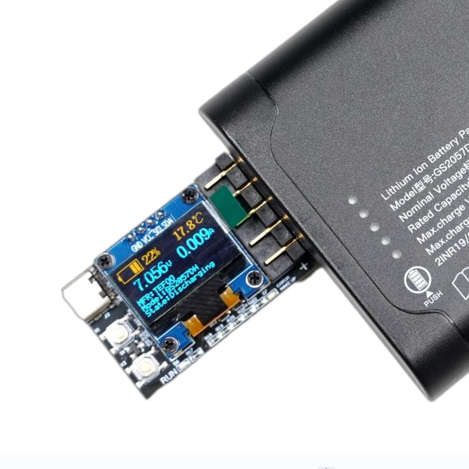
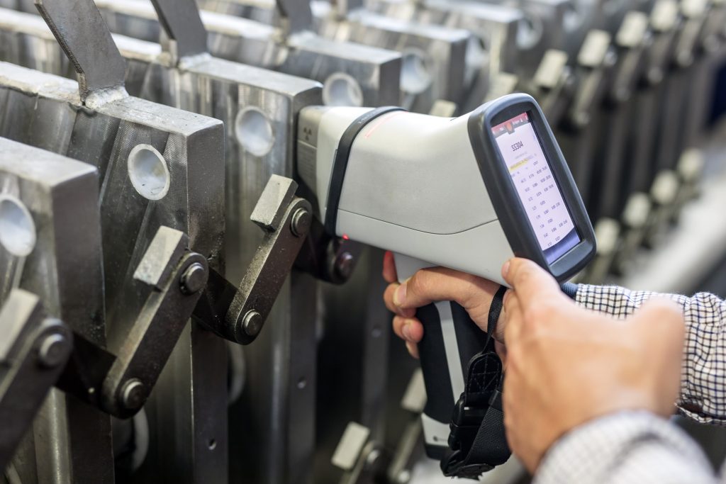
With the increasing power consumption of portable devices, the standby time of the device has become one of the key performance indicators of the product. The following factors affect the battery and power supply system design of portable devices:
1. The International Air Transport Association requires that the spare lithium batteries (including power banks) required by the equipment, when carried as hand or carry-on luggage, the rated energy of lithium batteries should not exceed 100Wh. The use of portable devices with lithium batteries exceeding 100Wh is very inconvenient in daily work and travel;
2. China’s “Dangerous Goods Transportation Regulations” and international related standards, when the energy of a single lithium battery exceeds 100Wh or the mass exceeds 1kg, and the total energy of the device exceeds 300Wh, a dangerous goods certificate must be obtained, and a dedicated dangerous goods box must be used for packaging and transportation. This means that the use of a single lithium battery exceeding 100Wh will be greatly restricted in export and transportation, greatly increasing labor and logistics, and time costs.
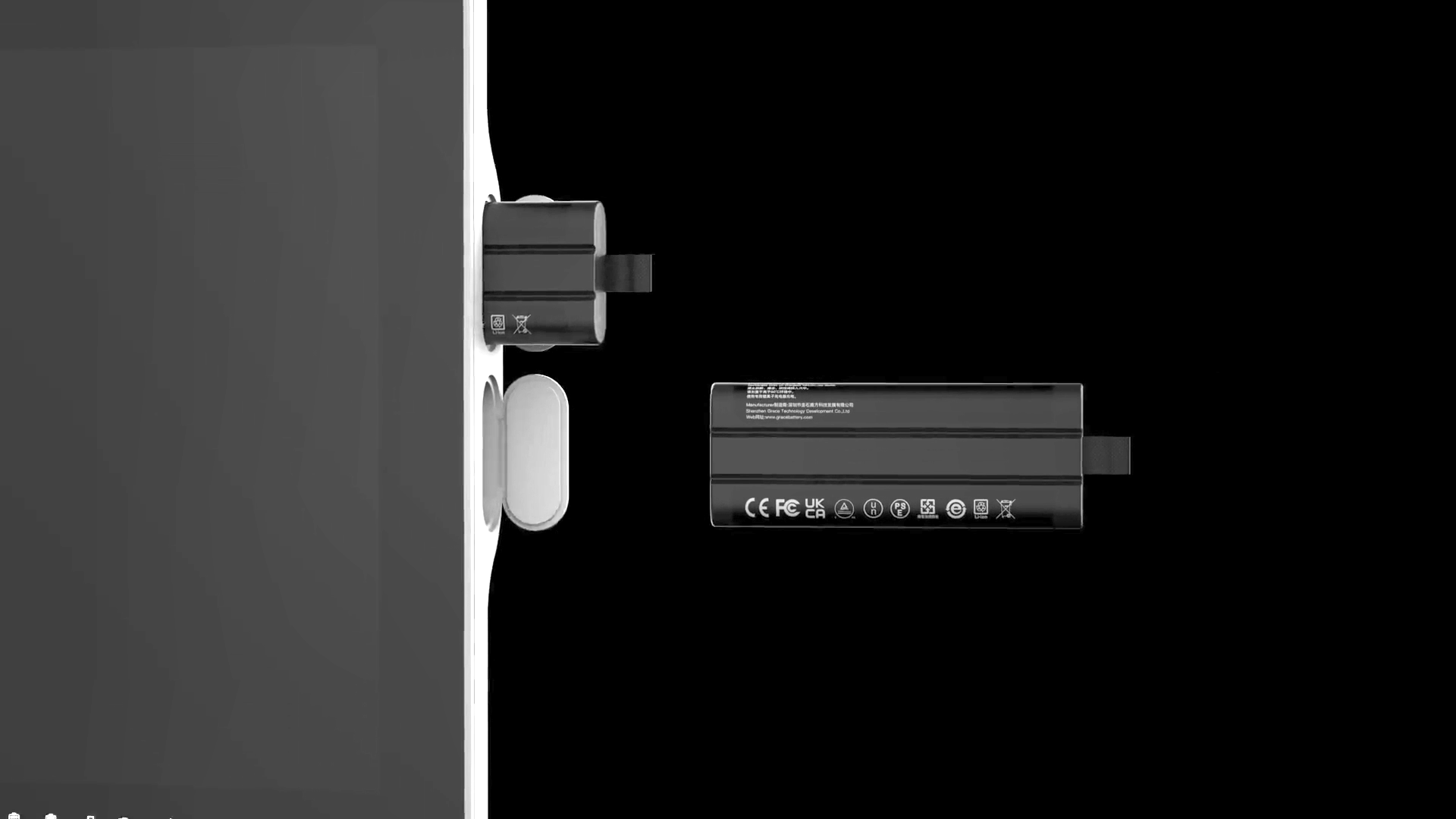
3. Due to the structural design limitations of portable devices, it is not possible to simply increase the capacity of a single lithium battery to increase the endurance time. It is necessary to distribute two single batteries in two positions of the host;
4. The power supply power required by portable devices is relatively large, and a single battery cannot support the system power, so dual batteries need to be connected in parallel for power supply at the same time.
5. Portable devices use batteries as the only power source, but they need to work continuously without interruption. A dual or more battery system can support the removal of any one of the batteries while the system remains powered on, achieving uninterrupted work by hot swapping the batteries.
6. In medical devices or other serious application fields, it is required that after a single battery fails, the system can still work normally. Therefore, a dual or more battery backup is needed to increase the reliability of the system power supply.
In summary, the demand for dual battery power supply is not uncommon. If the power supply demand of portable devices exceeds 100Wh, and battery technology has not made a breakthrough, choosing 2 or more standard batteries of 100Wh or less to form a multi-battery system has become the optimal solution.
In addition, standard batteries have all passed the UN38.3/MSDS certification test, which can meet the rapid and legal export and sale of portable devices, shortening the device listing time. The accompanying dual-chamber battery charger can help customers to use more conveniently in multi-battery applications.
Since the voltage and internal resistance of lithium batteries vary after being grouped, and the daily use conditions will further deteriorate the consistency of the battery group, the same model of lithium battery packs cannot be directly connected in parallel, otherwise the high-voltage battery will pour current into the low-voltage battery, resulting in safety risks. Therefore, a reasonable multi-battery management circuit must be designed to ensure the safe and reliable operation of the power supply system.
This article introduces the power supply architecture of dual or multi-battery power supply, provides a reference design block diagram and scheme recommendation, supports battery hot swapping, and uninterrupted power supply for the system.
**Solution One: Integrated Dual Battery Solution**
In response to the market demand for dual battery applications, Analog Devices, a well-known analog device semiconductor manufacturer, already has mature integrated circuits available for direct selection.
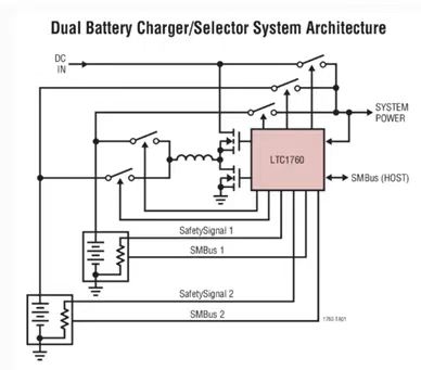
The LTC1760 is a comprehensive representative of a single-chip dual smart battery system, simple and easy to use, only requiring the determination of 4 parameters to complete a complete design, and no software code is needed. The device only needs the minimum amount of development work to form a complete dual battery charging and discharging system and work normally.
For details: https://www.analog.com/cn/products/ltc1760.html#part-details
**SolutionTwo: Discrete Dual Battery or Multi-Battery System**
For 3 or more batteries power supply systems, there is currently no integrated solution available for direct selection on the market. It is necessary to use existing technology to design a dual or multi-power supply structure with the main battery power path and backup battery power path as backups.
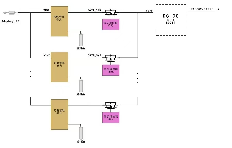
Mainly includes:
**Charging Management Unit:** To achieve constant current, constant voltage charging management of lithium battery packs, and system power supply path management.
Reference selection: TI company’s BQ24610.
**Anti-Reverse Current Control Unit:** To achieve the unidirectional conductivity of battery discharge, avoiding reverse current between multiple batteries, using an ideal diode (ORING controller).
Reference selection: TI company’s LM74700-Q1.
**DC/DC Constant Voltage Output Unit (Optional):** If the host system requires a fixed voltage power supply, a DC/DC module can be added on this basis. If the host can accept a wide voltage input, there is no need for this unit.
Reference selection: TI company’s LM5176PWPX.
**Please pay attention to the following**
♦ The input power supply power must be ≥ the maximum charging power of the dual batteries + the maximum operating power of the device, and consider the DC/DC loss, the input power supply power should be 1.2 times the sum of the two.
♦ When there is only one battery, it may not support the maximum discharge power.
♦ The battery voltage output is not a constant value. When the input power supply is powered on, VSYS (system power) equals the input voltage; when the adapter is powered off, VSYS voltage will equal the battery voltage. If the host requires a constant voltage power supply, a DC/DC conversion circuit is needed after VSYS.
♦ Using scheme two, the host cannot actively control the discharge sequence of the two batteries. When charging, they charge at the same time, and when discharging, the high-voltage battery will discharge first. The two batteries may be discharged at the same time, causing the system to lose power.
♦ Using scheme two, the smart batteries have the same communication address. The host needs two or more SMBUS/I2C interfaces to communicate with the batteries.
Note: The above is a limited technical experience summary by our company’s technical staff, aiming to provide application suggestions for multi-battery use. It does not represent a commitment or responsibility. The multi-battery power management system requires the equipment manufacturer to have certain power hardware development capabilities. It is designed according to the actual situation of the host itself. Our company can only provide limited technical consultation and cannot provide specific schematics, debugging and other services.