-260719-4-edited.png)

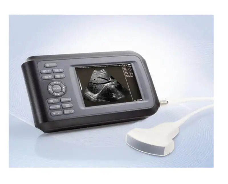
Handheld ultrasound has moved from a backup imaging tool to a primary point-of-care modality in emergency medicine, obstetrics, anesthesia, and veterinary practice. As the form factor shrinks from cart-based consoles to palm-sized smart probes, the power source can no longer be a “good enough” lithium pack with a voltage tap. It must be a smart battery compliant with the Smart Battery System (SBS) specification, communicating over SMBus so the host ultrasound platform can report accurate remaining runtime, anticipate charge cycles, and trigger safe-shutdown logic before a scan is interrupted mid-acquisition.
This guide walks through the engineering rationale, the SBS protocol layer, the medical-grade compliance stack, typical pack architectures, and the design pitfalls that most OEM programs encounter on their first revision.
1. The Power Problem Behind Handheld Ultrasound
Cart-based ultrasound systems treat the battery as a UPS-style backup: the unit runs on wall power most of the time, and the pack keeps the system alive long enough to save data during a power interruption. Runtime accuracy is a secondary concern.
A handheld unit inverts that assumption. The battery is the primary energy source. A clinician performing a fast echocardiogram in an ER bay, or a bedside vascular assessment in a ward, cannot afford to be told “15 minutes remaining” and then have the unit die at minute nine. They also cannot afford a pack that overheats in a coat pocket, swells inside a sealed enclosure, or fails to authenticate when a clinician swaps in a spare mid-shift.
Typical power profiles for a handheld ultrasound range from 8 W to 25 W continuous, with transient peaks up to 40 W during beamforming bursts and Doppler activation. Imaging modes (B-mode, M-mode, color Doppler, pulsed-wave Doppler) draw very different current profiles, which means a simple voltage-based fuel gauge — the approach used in consumer electronics that do not need SBS — will drift badly across modes. The host needs the battery to report RemainingCapacity and RunTimeToEmpty in real time, corrected for the actual discharge rate, temperature, and cell impedance drift over cycle life.
2. Why SMBus / SBS Is the Correct Architecture
The System Management Bus (SMBus), originally defined by Intel in 1995 and now maintained through SMBus 3.3, is a two-wire serial interface built on I²C physical signaling but with stricter electrical and timing rules for power-management devices. Layered on top of it, the Smart Battery System Implementers Forum (SBS-IF) defines the Smart Battery Data Specification (SBDS), which standardizes how a battery pack exposes its state to a host and to a smart charger.
For a handheld ultrasound OEM, adopting SBS rather than a custom analog gauge delivers three concrete engineering advantages:
- Predictable host software integration. The ultrasound firmware team reads the same register map — RemainingCapacity(), FullChargeCapacity(), RunTimeToEmpty(), Temperature(), Voltage(), Current() — that they would use for any SBS-compliant device. They do not need to write a bespoke driver for each battery supplier.
- Smart charger interoperability. A charger that speaks the Smart Battery Charger (SBC) spec reads the battery’s ChargingVoltage() and ChargingCurrent() commands and adjusts the charge profile per cell chemistry and temperature, rather than applying a fixed CC/CV curve. This is what enables the 0–90% fast-charge targets (30–40 minutes) seen in modern handheld probes, while keeping charge current throttled below 10 °C.
- Authenticity and lifecycle data. SBS standard registers include SerialNumber(), ManufactureDate(), CycleCount(), and ManufacturerName(). For a medical device subject to ISO 13485 traceability, this gives the quality team a machine-readable audit trail on every pack, directly linked to the device’s unique device identification (UDI) record.
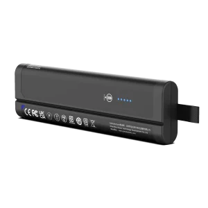
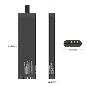
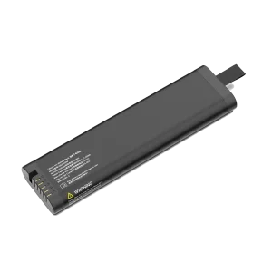
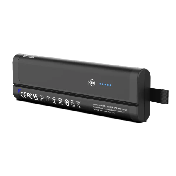
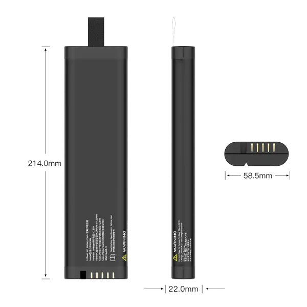
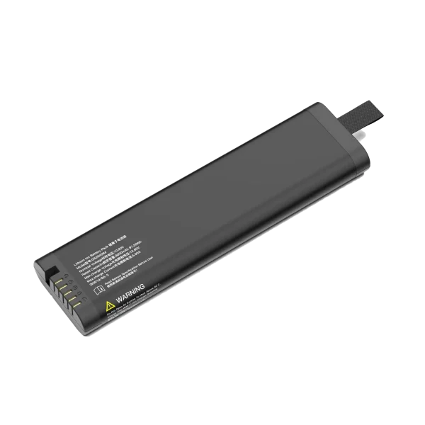
GS2040IM
10.8V/9300mAh/97.2Wh
3. SMBus / SBS Technical Deep Dive
3.1 Electrical and Protocol Layer
SMBus 1.1 and later versions operate at 3.3 V or 5 V ±10% logic levels, with a maximum bus clock of 100 kHz (SMBus 3.x supports up to 400 kHz and 1 MHz with HD mode). The physical layer uses two open-drain lines — SMBC (clock) and SMBD (data) — pulled up by resistors on the host side. A smart battery is a self-powered device: it runs its fuel-gauge MCU from its own cells, not from the bus VDD, which means it can communicate even when the host is off or in sleep.
One behavior that catches out first-time integrators: the SBDS requires the battery to enter an off state when both SMBC and SMBD are held low for more than 2 seconds. This is the deep-sleep mechanism that prevents a packed-and-shipped battery from draining itself on a logistics truck. When the host wakes the bus by releasing the lines, the pack must be ready to respond within 1 ms. If your ultrasound firmware polls the bus too aggressively during shutdown, you can accidentally force the pack into off state and create a “won’t wake up” field failure.
3.2 The SBS Registers That Matter for Ultrasound
Not every SBS register is equally important. The following table lists the registers that the ultrasound host firmware actually reads during a typical scan session, and what the UI displays to the clinician.
| SBS Register | SMBus Cmd | What the Host Uses It For | Typical UI Output |
| RemainingCapacity() | 0x0F | Absolute capacity left in mAh (or 10 mWh units), corrected for rate and temperature | Battery percentage icon |
| RunTimeToEmpty() | 0x11 | Estimated minutes left at present discharge current; updated every few seconds | “42 min remaining” banner |
| RunTimeToFull() | 0x10 | Estimated charge-completion time when docked | “Charge full in 25 min” |
| AtRateTimeToEmpty() | 0x06 | What-if runtime at a user-set future current draw (e.g., heavy Doppler mode) | Mode-specific runtime estimate |
| Temperature() | 0x08 | Pack thermistor reading in 0.1 K units; triggers thermal warning at >45 °C | Thermal warning toast |
| CycleCount() | 0x17 | Lifetime charge/discharge cycles; used by service team for battery replacement scheduling | Service menu only |
| BatteryStatus() | 0x16 | Alarm bits: over-charged, over-temp, over-current, remaining-capacity alarm | Safe-shutdown logic trigger |
3.3 Fuel Gauging Accuracy and Impedance Tracking
The difference between a consumer-grade SBS pack and a medical-grade one shows up in the absolute error on RemainingCapacity(). The SBS-IF Data Accuracy Testing Guidelines (Revision 2.0) define the test protocol, but they explicitly note that the original tests were written for notebook computers. For a handheld ultrasound, we recommend tightening the acceptance criteria:
- State-of-charge error < 3% at 25 °C across the 20–80% SoC window, after a full charge learning cycle.
- Run-time-to-empty error < 5% at the ultrasound system’s typical operating current (1.5–4 A for most palm-sized units).
- Temperature compensation verified at 0 °C, 25 °C, and 40 °C — because a pack left in an ambulance bay in winter will read optimistically if the gauge is not temperature-compensated.
Modern fuel-gauge ICs from Texas Instruments (bq27xxx series) and NXP use Impedance Track™-style algorithms that model each cell’s internal resistance as a function of SoC, temperature, and cycle count. This is what keeps the gauge accurate at cycle 300, when raw voltage-based methods have drifted by 15% or more. For a medical device with a 3–5 year service life, choosing a gauge that supports impedance tracking — and burning in the correct cell chemistry profile during production — is non-negotiable.
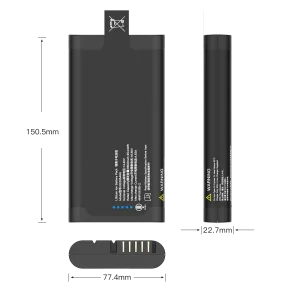
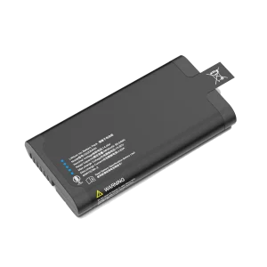
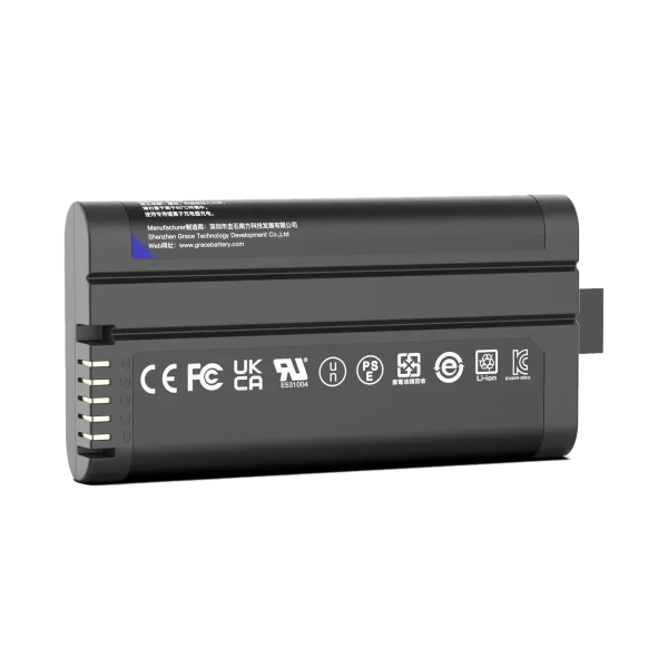
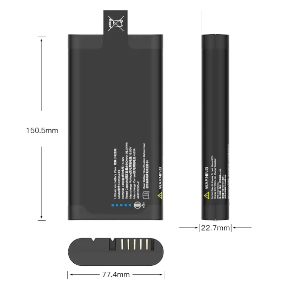
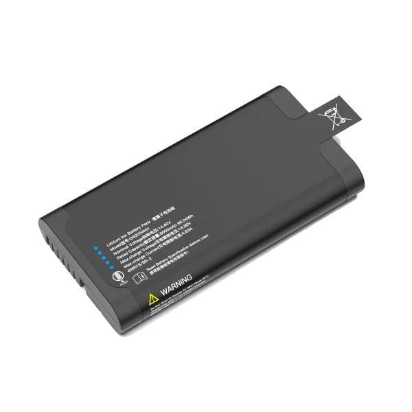
GS2054HH
14.4V/6900mAh/95.04Wh
4. The Medical-Grade Compliance Stack
An SBS-compliant pack that passes a consumer smoke test is not automatically a medical pack. The compliance stack for a handheld ultrasound battery spans four layers, each with its own test report and file entry in the device’s technical documentation.
| Standard | Scope | What It Requires for the Battery Pack | Market Relevance |
| IEC 62133-2 Ed 1.1 (2021) | Safety of portable sealed secondary lithium cells | External short-circuit, free-fall, thermal abuse, over-charge, forced discharge, and low-pressure tests. Part 2 covers lithium systems. | Recognized by FDA as a consensus standard; required for CE marking of medical EEE. |
| UL 2054 | Household and commercial battery packs | Additional enclosure, impact, and crush tests beyond IEC 62133; commonly requested by US hospital procurement. | North America market entry; many IDNs require it even when not legally mandated. |
| UL 1642 | Lithium cell safety | Cell-level safety testing; the pack manufacturer sources cells already certified to UL 1642. | Required in the pack’s technical file; supports due-diligence defense. |
| ISO 13485 | Medical device QMS | The pack supplier must operate under a quality management system with design controls, traceability, and change-notification procedures. | Required for FDA QSR equivalence and EU MDR conformity. |
| UN 38.3 | Lithium battery transport | Altitude simulation, thermal cycle, vibration, shock, short circuit, impact, overcharge, forced discharge — all eight tests before any shipment by air, sea, or road. | Global logistics; no exemption below the 100 Wh threshold applies to medical packs in practice. |
| IEC 60601-1 (clause relevant to power supply) | Medical electrical equipment general safety | The battery pack forms part of the ME device; the BMS protection circuit must meet the required isolation and creepage/clearance distances. | CE marking and FDA 510(k) submission baseline. |
4.1 FDA Recognition and Risk File Integration
The FDA recognizes IEC 62133 Ed 2.0 (and its consolidated revisions) as a consensus standard for secondary lithium cells used in portable medical applications. This does not mean a 510(k) reviewer will wave through any pack that carries the IEC 62133 test report. The battery must be treated as a risk-control measure in the device’s ISO 14971 risk file: the failure modes (short circuit, overheating, swelling, unexpected shutdown) must be identified, the BMS protections cited as controls, and the residual risk accepted in writing by the clinical engineering team.
This is where an OEM that works with a pack supplier experienced in medical programs saves months. A consumer battery vendor can hand over a pretty IEC 62133 report but will not provide the design-history file, the change-notification SLA, or the traceability matrix that the notified body expects.
5. Typical Pack Architecture and Configuration Selection
Handheld ultrasound form factors fall into two broad classes, and each pulls a different battery architecture.
5.1 Smart Probe Class (1S or 2S)
The palm-sized smart probe — think of a device that looks like a thick TV remote, with a transducer head on one end and Bluetooth/Wi-Fi offload to a tablet — typically draws 3–8 W. These units use 1S or 2S lithium-polymer pouch cells, often 1500–3500 mAh, because the form factor is so constrained that cylindrical cells would not fit. The pack lives inside the handle, and the clinician does not replace it in the field; it charges via USB-C or a wireless dock.
The TE Air-class reference design from Mindray, for example, uses a 3.85 V, 1650 mAh single-cell pack with USB-PD fast charging to 90% in under 35 minutes. For this class, the SMBus interface is often implemented on a compact gauge IC in a CSP package, because board space inside the handle is measured in millimeters.
5.2 Full Handheld Unit Class (3S, 4S, or 5S)
The larger handheld ultrasound — with its own screen, physical controls, and a transducer port — draws 12–25 W and needs 2–5 hours of continuous scanning. These units typically use 3S or 4S lithium-ion configurations, either 18650 cylindrical cells or larger prismatic/pouch cells, at 2500–6800 mAh capacity. Many designs use a dual-battery bay with a hot-swap selector compliant with the Smart Battery Selector Specification (SBS-IF), so a clinician can swap a depleted pack for a charged one without shutting down the unit and losing the live scan.
| Config | Nominal V | Typical Capacity | Energy Range | Best Fit |
| 1S | 3.6–3.85 V | 1500–3000 mAh | 5.5–11.5 Wh | Smart probes, phone-style ultrasound |
| 2S | 7.2–7.7 V | 2000–4000 mAh | 14–30 Wh | Compact handheld with small screen |
| 3S | 10.8–11.55 V | 2500–5200 mAh | 27–60 Wh | Mid-size handheld, primary scan unit |
| 4S | 14.4–15.4 V | 3000–6800 mAh | 43–105 Wh | Full-featured handheld, color Doppler |
5.3 Cell Chemistry Trade-offs
NMC (nickel-manganese-cobalt) pouch cells dominate this space because they offer the best energy density per cubic centimeter, which directly translates to longer runtime in a fixed enclosure. NCA is a secondary option for premium designs. LiFePO4 is rarely chosen for handheld ultrasound — its lower energy density (about 30% lower than NMC at the pack level) costs too much runtime, even though its thermal stability is better. The BMS protection circuit is expected to handle the safety case for NMC; asking the cell chemistry to carry that burden is the wrong engineering trade.
6. Eight Design Pitfalls We See in First-Revision Programs
After fifteen years of medical battery programs, the same mistakes recur in nearly every OEM’s first prototype build. Listed in order of how often we encounter them:
1. Treating the battery as a late-stage add-on. The ultrasound industrial designer locks the enclosure geometry before the battery pack is sized, then asks the electrical team to “fit something in the leftover space.” This almost always produces a pack that is thermally marginal and mechanically swollen-tolerant. Start the battery program at the same time as the enclosure layout.
2. Using a consumer fuel-gauge profile without cell matching. The gauge IC needs a chemistry profile matched to the actual cell’s discharge curve. Loading a generic NMC profile from the gauge vendor’s database produces 8–12% SoC error at the ultrasound’s high-current pulses. Budget for a characterization run.
3. Ignoring the SMBus off-state timing. As noted in §3.1, holding both lines low for 2 seconds puts the pack to sleep. Host firmware that does a slow shutdown sequence with the bus pulled low will create field failures that look like “battery won’t charge.”
4. Under-specifying the thermistor network. A single NTC on the PCB near the gauge IC does not represent the actual cell temperature in a tightly packed enclosure. Use at least one thermistor bonded to the cell surface, and make sure the SBS Temperature() register reflects it.
5. Forgetting the remaining-capacity alarm. SBS standardizes RemainingCapacityAlarm() (0x01) — a threshold you can set so the pack itself alerts the host when capacity drops below, say, 10% RRT. Without using it, the host can miss the alarm if its bus polling stops during a heavy imaging frame.
6. Choosing a pack vendor without ISO 13485 certification. The cost difference on unit price is 5–10%; the cost of a notified-body audit finding is four months of schedule slip. Do not save pennies here.
7. Not designing for cell swelling tolerance. NMC pouch cells grow 3–8% in thickness over their cycle life. The enclosure must have clearance, and the mechanical retention must not crush the cell at end-of-life. This is a mechanical-engineering problem, not a battery problem.
8. Shipping without a UN 38.3 summary on every pack. Airlines and freight forwarders will reject a shipment that does not carry the test summary and the watt-hour marking on the pack label. This is a documentation failure, not an engineering one, but it stops shipments cold.
7. OEM Integration: What a Medical Battery Program Actually Looks Like
A typical handheld ultrasound battery development program at TEFOO runs through the following phases, and we share them here because OEMs new to medical often underestimate the timeline:
- Week 0–2: Requirements freeze — system voltage, peak current, runtime target, enclosure envelope, SMBus register requirements, target certifications.
- Week 2–6: EVT pack build — 5–10 units on bench to validate gauge accuracy, charge profile, and thermal behavior.
- Week 6–12: DVT — 30–50 units for reliability cycling, drop testing, and pre-scout certification testing against IEC 62133-2.
- Week 12–20: Certification and PVT — formal IEC 62133-2, UL 2054, UN 38.3 testing, followed by production-tuning of the fuel-gauge learning cycle on the line.
The critical path runs through certification testing, not through mechanical design. Picking a pack partner that already holds ISO 13485 and has the IEC 62133-2 test data on file for the chosen cell model shaves 6–8 weeks off the schedule.
8. What’s Next: Higher Density, Faster Charging, and Digital Twin Integration
Three trends are shaping the next generation of handheld ultrasound batteries:
Higher-energy-density cells. Silicon-anode and high-nickel chemistries are entering the medical supply chain, promising 20–30% more Wh/L within the same envelope. The caveat: these chemistries need tighter BMS voltage regulation and more conservative end-of-charge limits, which means the SBS charge-profile handoff to the smart charger becomes even more important.
USB-C Power Delivery as the primary charge path. As ultrasound units drop the dedicated charging dock in favor of USB-C, the SMBus pack must negotiate with a USB-PD controller rather than a dedicated smart charger. This is a newer design pattern; the SBS-IF community is still converging on the reference designs.
Battery digital twins and fleet analytics. Hospitals deploying hundreds of handheld units want to know, remotely, which packs are approaching end-of-life. The CycleCount() and FullChargeCapacity() registers — readable over SMBus at every dock event — feed into a fleet-management dashboard. This is not a regulatory requirement today, but it is becoming a procurement checkbox for large integrated delivery networks.
Conclusion
For a handheld ultrasound system, an SMBus smart battery is not a premium option — it is the architecture that makes accurate runtime prediction, safe fast-charging, medical-grade compliance, and long-term serviceability possible. The SBS specification provides the host-interface standard; IEC 62133-2, UL 2054, ISO 13485, and UN 38.3 provide the safety and quality backbone; and the choice of fuel-gauge algorithm, cell chemistry, and pack-engineering partner determines whether the program ships on time and survives the notified-body audit.
If you are starting a new handheld ultrasound platform, the engineering questions to answer at week one are: what is the actual power draw across every imaging mode, what is the enclosure envelope, and which pack partner already has the certifications and the SBS integration experience to avoid the eight pitfalls listed in §6. Everything else is optimization.
References and Further Reading
1. SBS-IF, Smart Battery Data Specification Revision 1.1 and associated errata. sbs-forum.org/specs
2. SMBus Implementers Forum, System Management Bus (SMBus) Specification Version 3.3, 2024. smbus.org/specs
3. SBS-IF, Smart Battery Data Accuracy Testing Guidelines Revision 2.0.
4. IEC 62133-2:2017+A1:2021, Secondary cells and batteries containing alkaline or other non-acid electrolytes — Safety requirements for portable sealed secondary lithium cells, and for batteries made from them — Part 2: Lithium systems.
5. FDA Recognized Consensus Standards database, entry for IEC 62133 Ed 2.0. accessdata.fda.gov
6. ISO 13485:2016, Medical devices — Quality management systems.
7. UN Manual of Tests and Criteria, Subsection 38.3, Revision and Criteria for lithium batteries.
8. Texas Instruments, bq20z70 SBS-compliant Gas Gauge with Impedance Track Technology, datasheet.
9. Texas Instruments, Powering Point-of-Care Ultrasound Devices, application report SSZT182.
10. NXP, SMBus Quick Start Guide, AN4471.