An engineering framework for collaborative robots industrial arms and humanoid robot joint modules
Executive Conclusion
A Robot Joint Battery is not a general purpose battery made smaller to fit inside a joint. It is a power system designed together with the motor gearbox drive inverter brake and structural housing. The first design inputs are the real motion cycle peak current regenerative energy temperature limit available volume and service model.
A reliable development sequence is to define the power and energy envelope from mission data, select the cell and series parallel topology, then close the design with BMS logic thermal paths mechanical constraints and system validation. This approach makes performance easier to reproduce in production certification and field service.
Why Robot Joint Batteries Are Difficult
A joint module may have a cylindrical annular or offset cavity. The battery must stay close to the load without interfering with bearings encoders brakes or wiring. Robot motion also contains frequent starts stops reversals and acceleration events, so the battery sees short high power pulses rather than a smooth constant current.
Energy can flow in both directions. During deceleration or load lowering, the motor may return energy to the DC bus. If the battery cannot accept that pulse, the drive must manage the excess through a braking resistor or another energy path. A Robot Joint Battery specification must therefore include charge pulses and regenerative operation.
Derive Battery Requirements from Mission Profiles
Break a complete motion cycle into acceleration constant speed deceleration holding and standby states. Log DC bus voltage current speed joint torque ambient temperature and battery case temperature together. Use a representative shift or continuous cycle window instead of a single laboratory motion peak.
| Design quantity | Question to answer | Battery specification output |
| Peak power | What is the highest torque and speed over the shortest interval | Peak discharge current and pulse duration |
| Continuous power | How long does high load persist in each cycle | Continuous current and thermal design point |
| Regenerative power | How much energy returns to the bus during deceleration | Pulse charge current and overvoltage strategy |
| Usable energy | How much runtime is required for a task or shift | Rated capacity SOC window and reserve |
| Mechanical envelope | What length diameter mass and inertia are available | Cell format module shape and retention method |
For a first estimate use P = U x I for the power boundary and E = integral of Pdt for cycle energy. The final selection must include drive efficiency cable drop low temperature derating aging reserve and the usable SOC window. Motor nameplate power multiplied by runtime is not enough.
Cell Chemistry and Topology
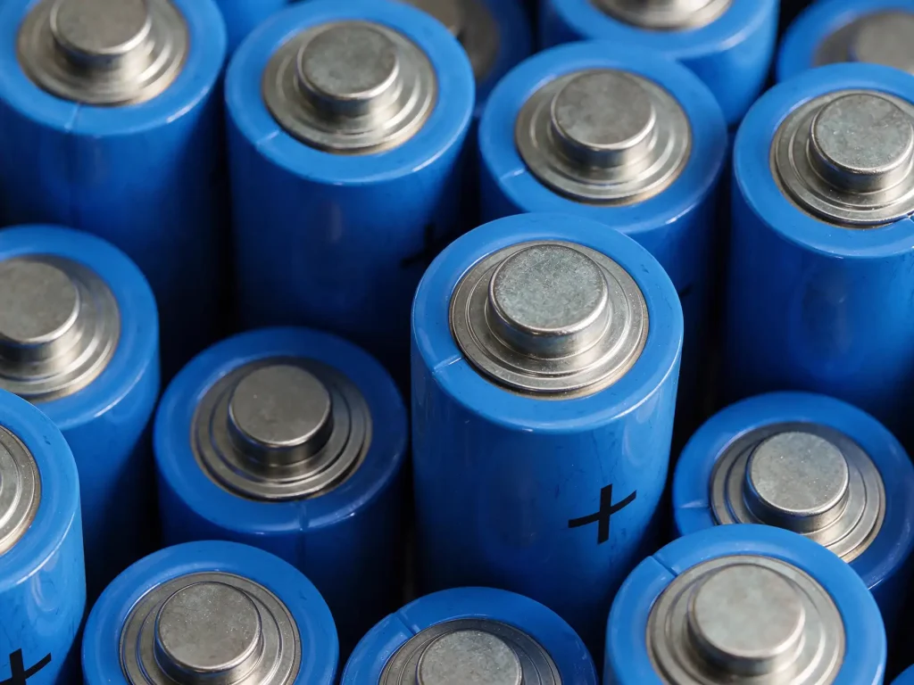
Robot joint projects often compare high nickel NMC cells lithium iron phosphate cells and high power cylindrical cells. High nickel chemistry can provide higher energy density, but high SOC storage and thermal control require more attention. LFP offers strong thermal stability and cycle life, but may require more volume or mass for the same energy. The decision should follow the safety target life model space limit and supply consistency.
| Route | Best fit priority | Engineering focus |
| High energy NMC | Very tight joint volume and runtime priority | Thermal isolation high SOC storage and cold temperature power |
| Lithium iron phosphate | Safety life and frequent cycling priority | Volume mass low temperature behavior and SOC window |
| High power cylindrical | Pulse power and supply stability priority | Parallel current sharing welds busbar heating and fusing |
Series count follows the bus voltage. Parallel count follows continuous and peak current, cell C-rate and the thermal path. Parallel cells do not remove risk by themselves: resistance variation can create uneven current sharing, so busbars fuses sensing and welds must be validated in the assembled module.
BMS Design Priorities
The BMS must manage discharge charge and regeneration as separate operating states. Protection thresholds should use cell voltage temperature duration SOC SOH and current rate of change together. For short peaks, a pulse permission window with temperature derating and event logging gives the drive a predictable power limit and avoids repeated hard trips near the boundary.
- Voltage protection: coordinate cell overcharge overdischarge series imbalance and bus overvoltage.
- Current protection: distinguish continuous current short peaks and regenerative current, and log the trigger.
- Thermal protection: monitor cell hot spots connection areas and the housing or cooling interface.
- State estimation: combine coulomb counting with open circuit voltage load correction and temperature compensation.
- Communication: exchange allowed power fault level and remaining energy with the drive and define a safe lost communication state.
For quick swap joints, define power up self test hot swap limits log access and serial number traceability. In collaborative and humanoid robots, whether the controller can correctly interpret a battery fault is as important as the cell performance.
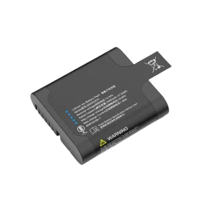
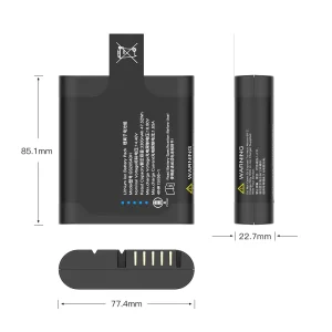
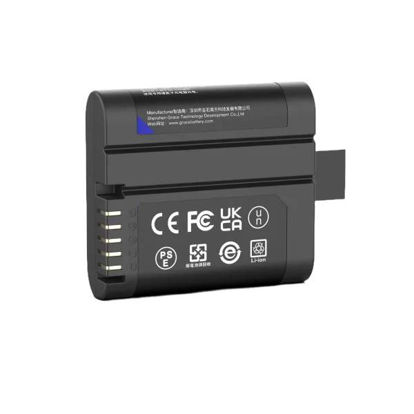
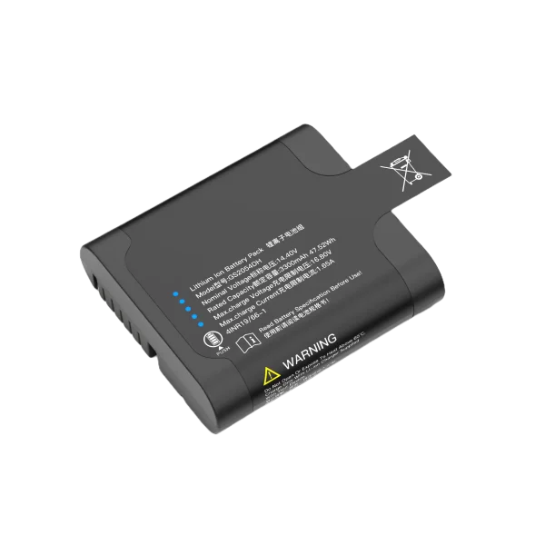
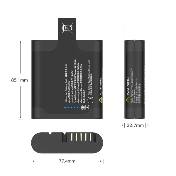
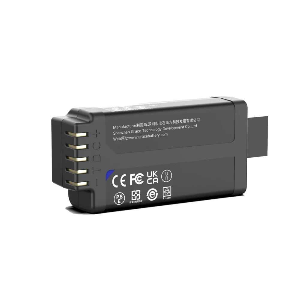
GS2054DH
14.4V/3450mAh/47.52Wh
Thermal Management and Mechanical Integration
The thermal problem inside a joint is often local heat concentration rather than high average power. Cell tabs busbars fuses connectors and housing contact areas can become hot spots. Build a thermal resistance path from the heat source to the housing and environment, then verify the assumptions with thermocouples or infrared measurements.
Mechanical design must address rotational inertia vibration shock and fatigue. Cells should not rely on adhesive alone to carry inertia. Compression structures insulating films cushioning materials fastener preload and anti wear paths require life testing. A battery mounted on a rotating member also needs checks for centrifugal force cable bend radius and rotary connector reliability.
- Include battery mass and rotational inertia in the joint motor and gearbox calculation.
- Maintain a stable load path and thermal interface across assembly tolerances.
- Define traceable tests for drops impacts vibration and repeated torsional motion.
Validation and Compliance Path
Validation must progress from usable cells to a deliverable system. A cell data sheet and single cell test establish a material boundary; they do not replace testing of the assembled pack BMS and joint. Use three test groups: design verification reliability verification and regulatory transport. Link sample ID software version test conditions and pass fail result.
| Stage | Typical work | Decision focus |
| Design verification | Capacity DC resistance peak power regenerative charge and temperature rise | Does it meet the motion cycle and protection boundary |
| Reliability verification | High low temperature vibration shock overcharge overdischarge short circuit and life | Failure modes derating curves and serviceability |
| Transport and regulatory | UN 38.3 and IEC 62133-2 applicability assessment | Sample consistency reports and traceability |
| Robot system | Emergency stop loss of communication braking collision and shift endurance | Does a fault reach a controlled safe state |
The applicable standard depends on product form market and transport mode. Passing one test does not equal full system compliance. IEC 62133-2, IEC 62619 and UN 38.3 are useful starting points for a requirements matrix. Industrial and collaborative robot projects should also consider ISO 10218 and ISO/TS 15066 for system safety.
Supplier RFQ Checklist
Before sending an RFQ to a cell or battery supplier, put the following information into a one page specification. The closer the specification is to the real motion profile, the more comparable quotations samples and validation results will be.
- Bus voltage range continuous power peak power and the duration of each peak.
- Charging method maximum charge current regenerative current and the time distribution of returned energy.
- Available joint space mounting direction mass limit rotational inertia and connector requirements.
- Ambient temperature humidity dust or liquid exposure vibration shock and target service life.
- Communication protocol fault levels log fields software update method and spare strategy.
- Target market transport mode certification scope materials requirements and traceability expectations.
Common Design Mistakes
Mistake one: comparing batteries only by ampere hours. Capacity does not describe peak power temperature rise or regenerative acceptance. Two batteries with the same capacity can behave very differently because of resistance thermal paths and BMS logic.
Mistake two: publishing a peak current without a time window. A peak must be tied to duration repetition interval initial SOC and temperature, or it cannot be reproduced.
Mistake three: treating a protection threshold as a control strategy. Repeated protection trips interrupt motion and create mechanical shock. The drive should receive an advance power limit and derating signal.
Mistake four: ignoring regeneration. Testing discharge without deceleration lowering and emergency stop can reveal bus overvoltage or charge limit failures only during system integration.
Frequently Asked Questions
How is a Robot Joint Battery different from a general robot battery
A general robot battery is often optimized for total runtime and replacement. A Robot Joint Battery must also fit the joint envelope, deliver pulse power, accept regenerative energy, control rotational inertia, survive structural fatigue and communicate with the drive in real time. It is a joint design between the pack and the actuator.
Should energy density be the first priority
Only after power temperature and safety boundaries are met. In frequent start stop or high regeneration applications, low resistance thermal control and cycle life may matter more than a higher Wh per kg value.
How can a buyer verify a supplier peak power claim
Ask for test temperature SOC pulse duration repetition interval cutoff voltage sample count and temperature rise. Reproduce the same conditions in acceptance testing. A maximum current without these conditions is not an engineering commitment.
When is liquid cooling needed
Consider active cooling when natural convection cannot keep hot spots within the cell and system limits during the worst motion cycle, or when a stable cooling loop already exists around the joint. Pumps tubes seals and maintenance add complexity, so decide with both thermal simulation and test data.
References and Official Sources
IEC 62133-2 Portable sealed secondary cells and batteries Part 2 Lithium systems Official source
IEC 62619 Secondary lithium cells and batteries for use in industrial applications Official source
UN Manual of Tests and Criteria Part III Subsection 38.3 Transport testing requirements for lithium cells and batteries Official source
ISO 10218-1 and ISO 10218-2 Safety requirements for industrial robots and robot systems Official source
ISO/TS 15066 Safety requirements for collaborative robot applications Official source