Executive summary
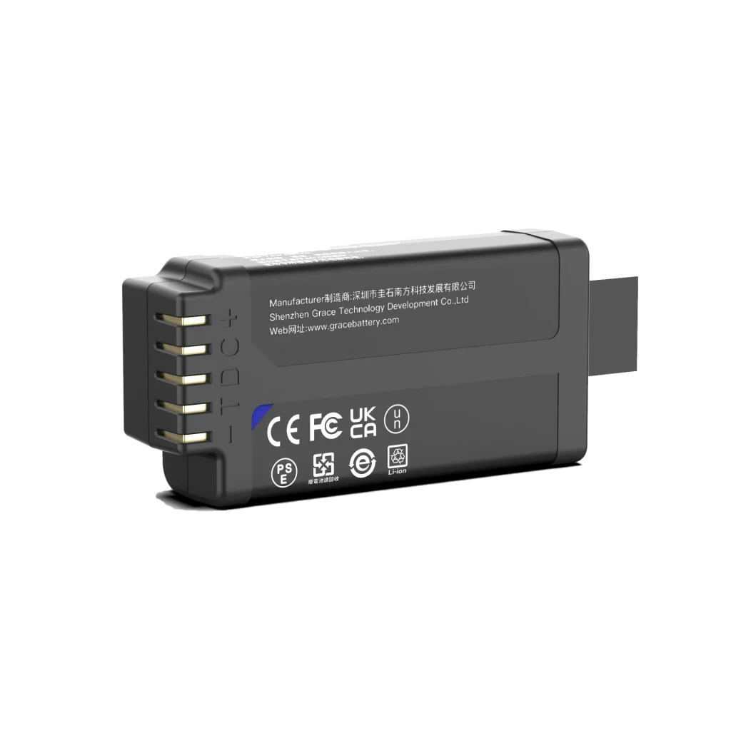
A portable blood gas analyzer battery pack must keep the analyzer operating through its complete workflow, including startup, sample handling, measurement, display, data transfer and an orderly shutdown. Nominal ampere-hours alone cannot establish runtime or reliability. Define the electrical and clinical workflow first, then size usable energy, prove transient power delivery, integrate protection and charging, and verify the finished pack in the analyzer across the intended temperature, aging and service conditions.
This guide is for product, electrical, mechanical, quality and sourcing teams developing portable blood gas analyzers. It explains the design decisions that connect a lithium-ion pack to a medical electrical system. Final limits must come from the analyzer requirements, selected cell documentation, risk management file and applicable market requirements.
Why a blood gas analyzer needs application specific battery design
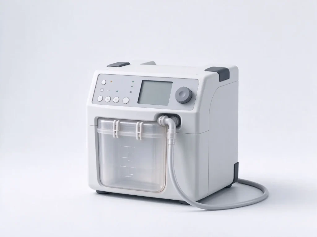
A portable analyzer may power pumps or valves, sample transport, sensors, temperature control, a processor, a display, memory and wired or wireless interfaces. Their current draw is not constant. A heater or pump can create a short high-load interval, while the instrument may spend much of its time in standby or awaiting a sample. The battery must satisfy both total energy demand and the minimum voltage required at each load during the most demanding event.
The use environment also changes the design target. Bedside, transport, emergency response and point-of-care workflows can differ in ambient temperature, charging access, movement, cleaning exposure and expected availability. The product team should translate each intended use into explicit operating and storage conditions before selecting cell chemistry or pack capacity.
1 Define the complete workload and runtime requirement
Build a state-based load profile from a representative analyzer. Measure current and voltage at the pack and, where practical, at critical subsystem rails. Include startup, self-test, measurement cycles, heater or pump activity, screen use, data storage, communications, idle periods, charging and shutdown. Record the duration and frequency of each state, including a realistic high-throughput workflow and the lowest expected battery state at which the analyzer must still complete a test.
Use measured profiles rather than a single average-current value. Repeat measurements with production-intent firmware and accessories. Include periods when a wireless link retries, a sensor or actuator is active for longer than usual, or a user leaves the screen on. These events can materially change energy use even when each one is brief.
A first-order energy estimate is:
Required nominal energy >= measured average load x target operating time / usable-energy fraction
The usable-energy fraction accounts for the permitted state-of-charge window, conversion losses, temperature, cell aging and engineering reserve. Define each factor from the product requirements and cell or pack test data. Avoid applying the same derating twice. Treat this equation as an initial sizing screen; confirm runtime with full-pack discharge testing in the analyzer.
2 Separate energy capacity from power capability
A pack can contain enough stored energy and still fail during a pump, heater or processor transient. At minimum cell voltage and low temperature, internal resistance rises and terminal voltage falls under load. Voltage loss also occurs across protection FETs, welds, connectors, wiring and the host power path. If the voltage at a subsystem drops below its operating limit, the analyzer may reset, interrupt a measurement or report a battery fault before the cells are empty.
Capture short load events with sufficient bandwidth to resolve their amplitude, duration and repetition rate. Calculate worst-case pack current at the minimum operating voltage, then test the waveform at cold temperature, low state of charge and representative aged impedance. Measure at the analyzer input and critical rails so the team can distinguish cell sag from converter response or interconnect losses. Verify that normal workload peaks do not trigger protection limits; hardware cutoffs should remain reserved for abnormal conditions.
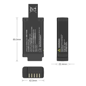
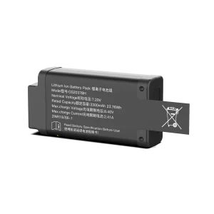
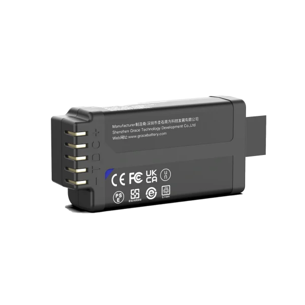
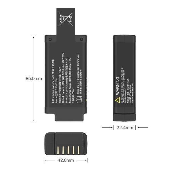
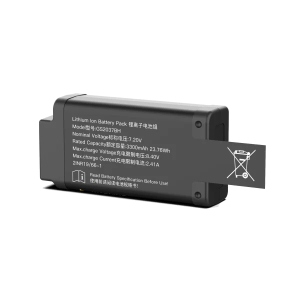
3 Select cells and configure the pack around the voltage window
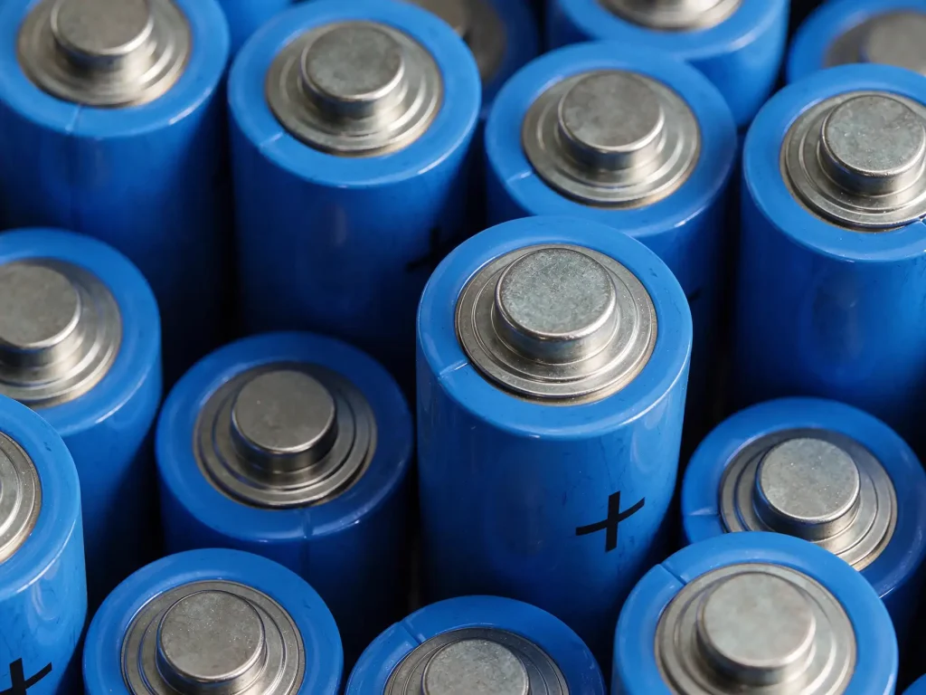
Compare candidate rechargeable cells using their actual datasheets and qualification evidence. Review usable capacity at the intended current and temperature, pulse and continuous current limits, charge limits, cycle-life conditions, storage guidance, impedance, dimensional tolerance and traceability. Chemistry labels alone do not establish suitability. The selected model and manufacturing controls matter more than a generic chemistry comparison.
Choose the series count to fit the complete input-voltage window of the analyzer and charger, including maximum charge voltage and minimum voltage under load. Choose parallel capacity from both runtime and worst-case current. Check cell balance, fault behavior and serviceability across the pack life. A larger capacity rating does not compensate for insufficient pulse capability, an unsuitable charger or excessive voltage drop in the power path.
4 Integrate the BMS, charger and analyzer firmware
For rechargeable lithium-ion packs, the battery management system (BMS) typically measures cell or pack voltage and temperature and provides protection functions appropriate to the pack architecture. Depending on the design, it may also estimate state of charge (SOC) and state of health (SOH), report faults and support cell balancing. Define charge, discharge and temperature limits from the selected cell documentation and the product risk analysis. Include BMS standby current in the runtime budget.
The charger must use a charge profile compatible with the cell configuration and must coordinate with pack protection, temperature sensing and the analyzer’s operating states. Define whether the analyzer may perform tests while charging, how charging is indicated, and what happens after an interrupted or failed charge. Verify connector polarity, insertion behavior, contact temperature and fault response with the intended accessories and service process.
Firmware should warn early enough to preserve a completed measurement and stored patient data. Define battery-low thresholds using validated SOC accuracy under the analyzer’s variable load. Test the user-visible response to low charge, pack communication loss, sensor faults and sudden voltage sag. Where the clinical workflow allows, the instrument may defer nonessential activity or request connection to external power before a controlled shutdown. The battery estimate is a maintenance aid, not a substitute for a validated operating limit.
5 Design thermal and mechanical integration for clinical use
Assess cell, BMS, charger and host heat during measurement, charging and simultaneous operation where the product permits it. Use the intended enclosure, insulation and mounting hardware, since these affect heat flow. Confirm that cell and pack temperatures remain within supplier limits under the worst supported ambient conditions. Keep sensors positioned to detect relevant cell temperatures rather than only nearby board temperature.
The enclosure should control movement without imposing damaging compression on cells, terminals or welds. Account for dimensional tolerance, vibration, drop, connector retention, cable strain, cleaning agents and fluid ingress appropriate to the intended use. Provide electrical insulation and a service method that prevents incorrect replacement. If a removable battery is used, design the latch, contacts and user feedback so that partial insertion or worn contacts cannot create an intermittent supply during a measurement.
6 Build verification around the finished analyzer
Verification should connect a defined requirement to a reproducible test and an acceptance criterion. Test the pack in the production-intent analyzer, not only on a cell cycler. Record cell model and lot, firmware, workload, ambient and pack temperature, charge state, measurement cadence, communications state and instrumentation for every runtime or transient result.
- Runtime and usable capacity under nominal and worst-case intended workflows, including low-charge completion and orderly shutdown.
- Transient response at low state of charge, low temperature and representative aged impedance, with voltage measured at the analyzer and critical rails.
- Charge behavior, temperature sensing, SOC indication, protection thresholds, fault reporting and recovery after interrupted power.
- Temperature rise during charging and operation, plus relevant mechanical, ingress, cleaning and connector endurance tests.
- Risk-control verification for battery faults, including short circuit, overcurrent, overtemperature and foreseeable misuse where applicable.
Medical electrical equipment assessment is system-specific. IEC 60601-1 addresses basic safety and essential performance of medical electrical equipment, while IEC 60601-1-2 addresses electromagnetic disturbances. A battery pack does not become compliant simply because it uses a certified cell or has passed transport testing. Determine the applicable standards and edition for the analyzer, battery architecture and destination market with the regulatory and test teams. UN Manual of Tests and Criteria subsection 38.3 covers lithium battery transport testing; it does not replace medical electrical equipment assessment or product safety evaluation.
7 Manage replacement, storage and end of life
Set a replacement policy using validated cycle and calendar aging evidence, expected storage conditions and field data. Specify storage charge state and inspection intervals from the cell supplier’s instructions and the product service model. Define what the analyzer displays when capacity estimates become unreliable or a pack reaches its service limit. Maintain lot traceability and a controlled process for returned, damaged or swollen packs, and provide disposal information that follows local requirements.
For fleet deployments, field logs can help compare estimated state of charge with measured runtime, charge interruptions and service returns. Use that evidence to refine warning thresholds and maintenance intervals through controlled design changes. Do not treat a runtime estimate from one workflow or cell lot as a universal guarantee.
Engineering takeaway
A dependable portable blood gas analyzer battery pack is sized from the analyzer’s measured workflow and qualified against the real power path. The design review should establish usable runtime, transient margin, safe charging, early warning behavior, thermal limits, mechanical protection and system-level compliance evidence. Those results give engineering and clinical teams a traceable basis for deciding whether the analyzer can complete its intended work on battery power.
Frequently asked questions
How do I estimate runtime for a portable blood gas analyzer battery pack?
Measure the analyzer’s energy use across representative startup, measurement, idle, display, communications and shutdown states. Apply justified allowances for conversion loss, usable discharge range, temperature, aging and reserve, then confirm runtime on the finished analyzer with production-intent firmware.
Why can an analyzer shut down while the battery indicator still shows charge?
A high-current event can pull pack voltage below the analyzer’s minimum input even when energy remains. Check cell impedance, temperature, state of charge, protection-path resistance, connector condition and voltage at the host during the event.
Can a battery pack be qualified separately from the analyzer?
Pack-level tests are useful for cell, protection and charging behavior, but they do not demonstrate complete system performance. Runtime, voltage margin, firmware response, essential performance and electromagnetic compatibility need evaluation in the applicable analyzer configuration.
Does UN 38.3 certify a battery for medical use?
No. UN 38.3 addresses lithium battery transport testing. Medical electrical equipment safety and performance are assessed under applicable product standards and market requirements, which are separate from transport qualification.
What information should a battery supplier provide?
Request the exact cell model and revision, datasheets, lot traceability, capacity and impedance limits, temperature-dependent charge and discharge limits, protection architecture, change-control process, test evidence and transport documentation. Confirm that the delivered pack matches the configuration evaluated in the analyzer.
References and technical basis
- International Electrotechnical Commission, IEC 60601-1, Medical electrical equipment, Part 1: General requirements for basic safety and essential performance. Confirm the applicable edition and amendments for the target market.
- International Electrotechnical Commission, IEC 60601-1-2, Medical electrical equipment, Part 1-2: General requirements for basic safety and essential performance, collateral standard: Electromagnetic disturbances. Confirm applicability and current edition.
- United Nations, Manual of Tests and Criteria, subsection 38.3, lithium metal and lithium ion batteries. Consult the current revision and applicable transport rules.
- Selected cell and BMS manufacturer datasheets, safety information and qualification records. Product-specific limits must be confirmed against the exact model and revision used in the pack.
Author perspective: Prepared from the perspective of a lithium-ion battery project engineering lead. The guidance is general and does not represent test results for a particular analyzer or battery product. The product team must verify all limits and regulatory applicability against the finished design and destination markets.