By Author · Senior R&D Engineer, Battery Systems · TEFOO | Published: October 2026
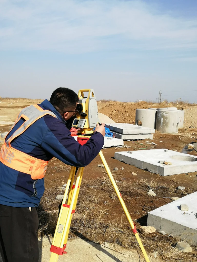
For decades, most scientific and test and measurement (T&M) instruments were designed around a wall outlet. Oscilloscopes, spectrum analyzers, signal generators, digital multimeters and data loggers sat on lab benches, tethered to mains power. That assumption is changing fast.
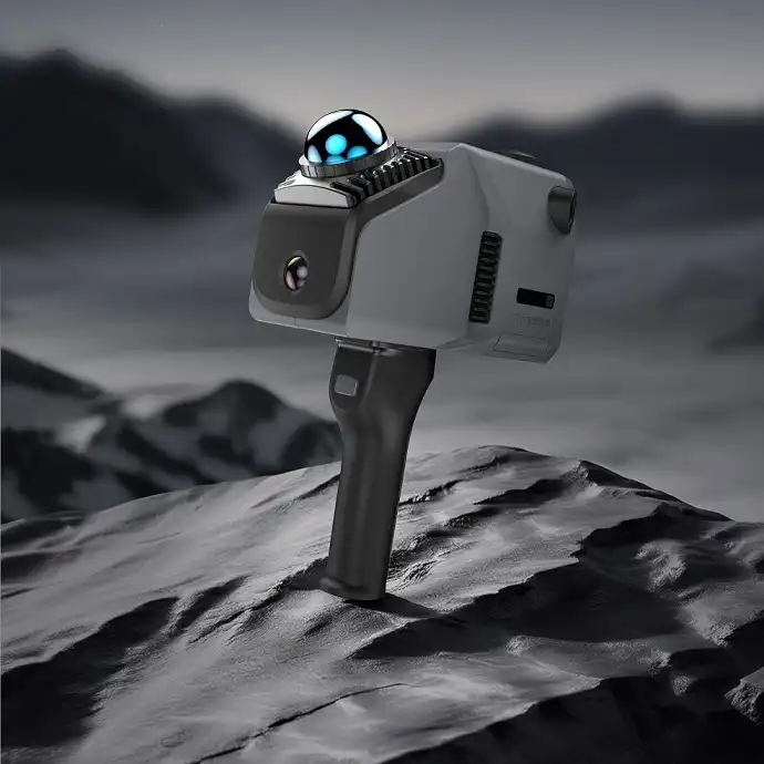
The global test and measurement market was valued at USD 19.84 billion in 2026 and is projected to reach USD 24.27 billion by 2031, a compound annual growth rate of 4.11% (Mordor Intelligence). The electrical test equipment segment alone is forecast to grow from USD 17.31 billion in 2026 to USD 23.15 billion by 2031 (Research and Markets). A growing share of that equipment is battery-powered: handheld multimeters, portable spectrum analyzers, field data loggers, non-destructive testing (NDT) instruments, thermal cameras and remote monitoring nodes. Even benchtop instruments increasingly carry an internal battery for isolation from mains noise and for ride-through power. Smart, IoT-connected multimeters that stream readings to the cloud are already a recognized market trend (Verified Market Reports).
As a lithium battery engineer who has spent years designing custom packs for professional instruments, I keep seeing the same mistake: treating the battery as an off-the-shelf commodity. In measurement equipment, the battery is a subsystem. It must deliver clean, stable power that does not corrupt a microvolt-level measurement; it must report its state accurately enough that a field technician trusts the runtime display; it must survive the temperature, vibration and duty cycle of real lab and field use; and it must carry the safety certifications that let you ship into your target markets. That is precisely what custom battery pack design is for.
Why a Purpose-Built Battery Pack Matters
The decision to design a custom pack is usually driven by one or more of the following gaps in commodity packs:
- Measurement accuracy and power quality. Precision front-ends inherit noise from their supply. Cell impedance, connector contact resistance and BMS switching transients can all inject ripple into sensitive measurement circuits. A custom pack lets you specify impedance targets, filtering and shielding.
- Real-world load profiles. Instruments rarely draw steady current. A data logger may idle at a few milliamps and then pull several amps during a wireless transmission or a motorized sweep. Packs sized only for average current can collapse under pulse loads; the design must start from the measured profile.
- Form factor and integration. The pack must fit your enclosure, connector and mounting scheme – every wasted cubic millimeter is margin lost elsewhere.
- Communication and telemetry. Professional instruments need the battery to talk: state of charge, health, temperature, cycle count and alarms, typically over SMBus, CAN or UART. The Smart Battery Data specification (Rev 1.1, SBS-IF) defines the command set; SMBus v3.3 defines the physical layer.
- Compliance ownership. The battery must be certified to IEC 62133-2 and UN 38.3, and – depending on market and application – UL 1642/UL 2054 or IEC 62619. If a supplier cannot show certificates for your exact configuration, the risk lands on your instrument project.
Table 1. Off-the-shelf pack vs. custom-designed pack
| Criterion | Off-the-shelf pack | Custom-designed pack |
| Mechanical fit | Compromise; may protrude or require an adapter | Designed to your enclosure, connector and mounting |
| Capacity and voltage | Fixed; you choose the nearest standard | Specified to your load profile and runtime target |
| Load capability | Rated for assumed loads | Designed for measured pulse and peak currents |
| Fuel gauge accuracy | Basic or none | Calibrated fuel gauge with Smart Battery Data (SMBus) reporting |
| Communications | Usually none | SMBus / CAN / UART, configurable alarms and telemetry |
| Thermal behavior | Unknown in your application | Simulated and tested in your operating environment |
| Certifications | Certificate for the pack, not your configuration | Certificates for your exact configuration (IEC 62133-2, UN 38.3, UL, IEC 62619) |
| Total cost of ownership | Low upfront; risk and rework later | Higher upfront; predictable field reliability |
None of this means standard packs are bad. For simple, low-cost consumer instruments they remain the right answer. The moment your instrument’s accuracy, runtime, communications, thermal environment or compliance profile becomes a requirement, a custom design stops being a luxury.
Core Design Considerations
Good custom battery design is a chain of decisions, each driven by the instrument’s real requirements. These are the seven areas where projects succeed or fail.
Start with the Load Profile
The design begins with data, not assumptions. We instrument the actual device and log continuous current, pulse peaks, duty cycle and the voltage window the instrument tolerates across charge and discharge. The load profile exposes what a datasheet cannot: the true peak-to-average ratio, which sets the C-rate requirement; the minimum voltage before brownout, which sets the series count and discharge curve; and the charging window available in the field, which sets charge-current limits. Ask your partner to make this measurement part of the project kickoff. It is the cheapest mistake-prevention step available.
Choose the Cell Chemistry Deliberately
The right chemistry is a trade-off among energy density, cycle life, rate capability, temperature behavior and cost – and the decision belongs to the instrument’s requirements, not to a catalog.
Table 2. Cell chemistry comparison for instrument battery packs
| Chemistry | Typical energy density | Typical cycle life | Rate capability | Low-temperature behavior | Best fit for |
| NMC (LiNiMnCoO₂) | ~250-270 Wh/kg (cell) | 500-1,000 cycles to 80% | 1-3C continuous, higher pulsed | Reduced below ~0 °C; heaters may be needed | Portable instruments where energy density and weight matter most |
| LFP (LiFePO₄) | ~160-190 Wh/kg (cell) | 2,000-5,000+ cycles | 1-5C continuous, good pulse | Moderate; usable with derating | Long-life, high-cycle or safety-critical instruments |
| High-rate cells (e.g., LTO) | ~60-130 Wh/kg (cell) | 5,000-20,000+ cycles (LTO) | 10C+ pulses | Excellent (LTO) | Instruments with strong pulsed or high-inrush loads in cold environments |
Note the voltage platforms: LFP cells sit at 3.2 V nominal versus 3.6-3.7 V for NMC. That difference changes the series count, the charger design and the instrument’s input range – another reason the cell decision should be made early, together with your hardware team.
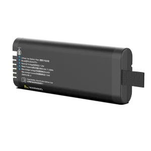
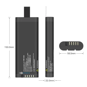
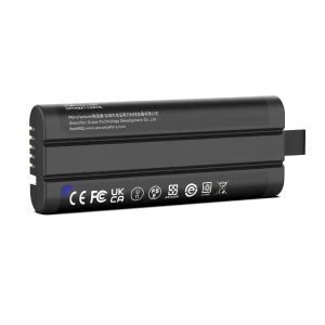
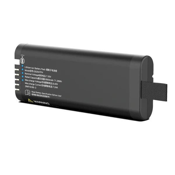
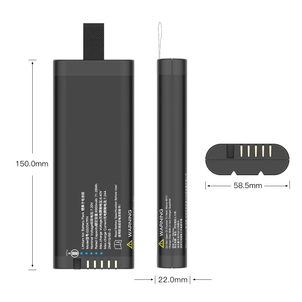
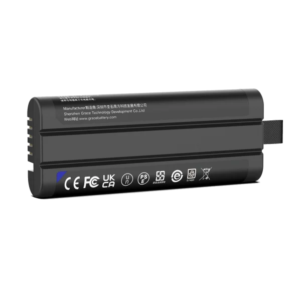
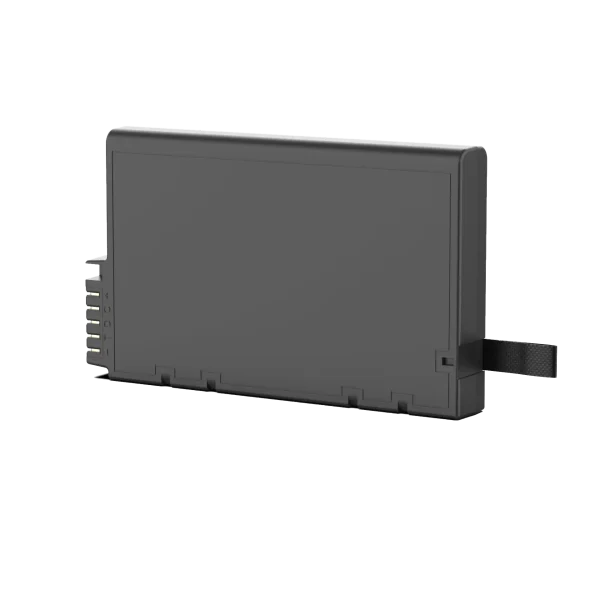
GS2047FH
7.2V/10350mAh/71.28Wh
Design the BMS as an Engineering Component
The BMS is where a custom pack earns its keep:
- Protection. Over-voltage, under-voltage, over-current, short-circuit and temperature cutoffs, with both hardware and firmware layers. Cutoff thresholds must be specifiable: a data logger that disconnects at the wrong threshold can silently lose weeks of field data.
- Fuel gauging. Professional instruments need accurate state of charge. A coulomb-counting gauge with open-circuit-voltage correction delivers the accuracy technicians expect. The Smart Battery Data command set (SBS-IF, Rev 1.1) defines the standard registers – remaining capacity, voltage, current, temperature and time-to-empty – exchanged over SMBus v3.3. If your instrument already speaks SMBus, the pack should behave like a standard smart battery.
- Alarms and telemetry. Configurable low-battery and critical alarms, cycle counting and abuse-event logging give your service team real diagnostics.
- Quiescent current. For instruments that sit on a shelf between jobs, BMS self-consumption must be minimized. A pack that drains itself in a month of storage becomes a field-service problem.
Manage Heat, Not Just Temperature
Most lithium cells charge between roughly 0 °C and 45 °C and discharge between roughly -20 °C and 60 °C, with chemistry-specific limits. In a sealed instrument, the battery often has the worst thermal path in the system. The engineering actions: thermal simulation of the pack inside your enclosure, NTC sensing on the hottest cells and on the BMS, charge-current derating above thresholds, and keeping the BMS away from heat sources. Thermal design done at the drawing stage costs nothing; retrofits cost a re-certification cycle.
Integrate Mechanical and EMC Design
The pack is part of the instrument’s electromagnetic environment. Measurement equipment is subject to EMC requirements under IEC 61326-1:2020, and the battery should not be the source of a failure: BMS switching transients, interconnect loops acting as antennas and unshielded harnesses can all couple into sensitive front-ends. Practical measures include separating power and signal traces in the harness, shielding the pack when needed, filtered connector pins and EMC pre-compliance testing of the pack-in-instrument combination. Mechanical integration covers connector selection rated for the true peak current, mounting that does not transmit vibration, and enclosure materials compatible with your flammability and ingress requirements.
Plan Safety and Certification from Day One
Safety is a design input, not an afterthought. For portable lithium packs, the baseline is IEC 62133-2:2017+AMD1:2021 (safety requirements for portable sealed secondary lithium cells and batteries). Transport requires UN 38.3 (Manual of Tests and Criteria, Section 38.3) for cells and pack. Depending on markets and application you will also encounter UL 1642 (cells), UL 2054 (portable batteries) and IEC 62619:2022 (industrial applications). The instrument itself is covered by IEC 61010-1:2010+AMD1:2016, the safety standard for electrical equipment for measurement, control and laboratory use. Market-entry marks such as CE, UKCA and CCC tie back to these standards, so the pack’s certificate must match your exact configuration. A serious partner designs for the certificate, not after it.
Engineer for the Full Service Life
Field instruments live for years, so cycle life and calendar life both matter – cycle life for daily users, calendar life for equipment that is charged, stored and used occasionally. Low self-discharge cells, minimized BMS quiescent draw, conservative charge voltage (for NMC, a ceiling slightly below 4.2 V per cell buys longevity) and a storage-optimized firmware state all extend service life. Define end-of-life acceptance early – 80% of rated capacity is the common convention – and make sure the fuel gauge stays accurate as the pack ages.
Choosing the Right Custom Battery Partner
The difference between a battery assembler and a battery design partner shows up in exactly the areas where custom packs succeed. Evaluate suppliers against these criteria:
Table 3. How to evaluate a custom battery partner
| Criterion | What to look for |
| Certification evidence | IEC 62133-2 and UN 38.3 reports for your configuration; UL 1642/UL 2054 or IEC 62619 where relevant; certificates issued in your company name where required. |
| BMS engineering depth | In-house BMS hardware and firmware; fuel-gauge expertise (Smart Battery Data / SMBus); configurable protection thresholds. |
| Communication protocols | Proven SMBus, CAN and UART integration experience with customer firmware teams. |
| Testing capability | In-house electrical, environmental, mechanical and EMC testing, or accredited labs; documented validation reports. |
| Documentation | Design specification, FMEA, schematics, firmware release notes and test reports delivered as part of the project. |
| Change management | Formal change notification and re-validation process for cell or component changes. |
| After-sales support | Field failure analysis, root-cause reporting and firmware or process updates over the product’s life. |
Treat the absence of these as red flags:
- No certification evidence beyond a generic claim on a sales page.
- A proposal that describes “cells, a protection board and shrink tube” – with no BMS engineering or fuel gauge.
- No thermal data for your operating environment.
- No willingness to sign an NDA or to document the design.
- A battery interface limited to two power leads, with no telemetry options.
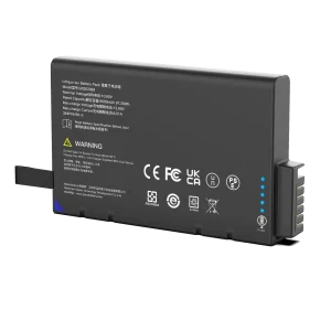
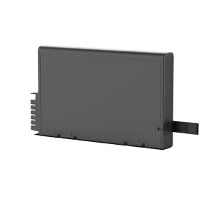
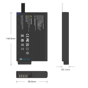
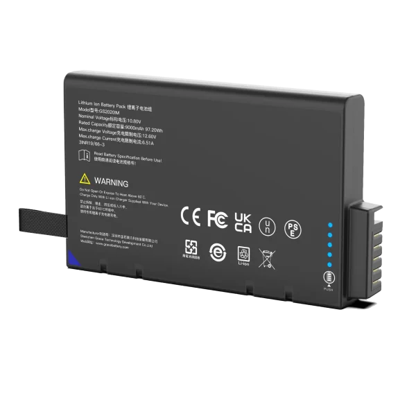
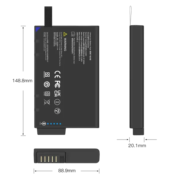
GS2020IM
10.8V/9300mAh/97.2Wh
From Specification to Production
A proven custom pack project follows a disciplined sequence:
- Requirements – measure the load profile; define voltage window, capacity target, dimensions, environment, certifications and communications.
- Feasibility – select chemistry, series/parallel configuration and BMS; run thermal simulation; lock schedule and cost.
- Design – mechanical CAD, harness and connector, BMS hardware, firmware with gauge calibration.
- Prototypes – engineering samples for your integration testing: measurement accuracy, charger compatibility and communications.
- Validation – electrical tests (protection trips, gauge accuracy), environmental (temperature, humidity, vibration), mechanical (drop) and EMC pre-compliance.
- Certification – IEC 62133-2, UN 38.3 and market-specific marks on the final configuration.
- Production – controlled cell sourcing (same manufacturer and grade), in-line and outgoing quality control.
- Support – documented design package, field failure analysis and lifecycle firmware updates.
A straightforward custom pack typically moves from requirements sign-off to validated prototype in 8-14 weeks; certification adds lead time depending on scope and laboratory.
Frequently Asked Questions
What do you need to start a custom battery pack design?
A complete picture of the instrument: the measured load profile, the allowed voltage window, capacity and runtime target, mechanical envelope, operating and storage temperatures, communications interface (SMBus, CAN or UART) and target certifications and markets. The more real data you share, the fewer assumptions we make.
How long does a custom pack project take?
A straightforward custom pack runs 8-14 weeks from requirements sign-off to validated prototype. Certification (IEC 62133-2, UN 38.3, UL, IEC 62619) adds lead time depending on scope and laboratory. We fix the schedule at the feasibility stage, not before.
Can you replace a standard pack inside existing equipment?
Often yes, but the replacement must be validated at the system level. Engineers should confirm nominal and maximum voltage, capacity, continuous and peak current, connector pinout, charging profile, communication protocol, physical dimensions, mounting method, thermal behavior and protection settings – and then test the complete instrument for startup behavior, measurement stability, charger compatibility and fault response.
Which certifications will my battery pack carry?
Baseline: IEC 62133-2:2017+AMD1:2021 for the pack and UN 38.3 for transport. For North America, UL 1642/UL 2054; for industrial applications, IEC 62619:2022. Market marks such as CE, UKCA or CCC are planned with you at the requirements stage so the certificate matches your exact configuration.
Can the battery communicate with our instrument?
Yes. We implement SMBus Smart Battery Data (Rev 1.1) as well as CAN, UART and I²C-based protocols. The register map, alarms and gauge calibration are defined together with your firmware team.
How do you keep the battery from interfering with sensitive measurements?
EMC is a design input, not a test surprise. We manage switching transients, harness routing and shielding, and run EMC pre-compliance testing of the pack in the instrument – in the context of IEC 61326-1:2020 – before final certification.
What service life can we expect?
It depends on chemistry and use. LFP packs typically deliver 2,000-5,000+ cycles; NMC packs around 500-1,000 cycles to 80% capacity; calendar life is typically 3-5+ years under sensible storage conditions. End-of-life criteria (usually 80% of rated capacity) are written into the design specification.
Do you support OEM/ODM branding?
Yes. Labels, markings, packaging and documentation can be produced under your brand, and we supply the engineering documentation – design specification, FMEA, test reports – that your quality organization needs.
Conclusion
The battery is often the difference between an instrument that works on paper and one that works in the field. For scientific and T&M equipment, that means designing from the measured load profile, choosing chemistry deliberately, engineering a smart BMS with accurate fuel gauging and SMBus communication, managing heat, planning certification from day one and working with a partner that does real engineering rather than assembly.
TEFOO designs and manufactures custom smart-BMS battery systems for medical and industrial OEMs – with SMBus communication, fuel-gauge integration and full OEM/ODM customization, backed by an engineering team in Shenzhen. If you are specifying a battery for a new instrument, or replacing a pack that keeps failing in the field, bring us your load profile and requirements – the design conversation starts there.
About the author: Author is a senior lithium battery R&D engineer at TEFOO, specializing in smart BMS architecture, fuel gauging and SMBus communication for medical and industrial OEM battery systems, with project experience spanning portable test and measurement, NDT and medical instruments.
Sources and References
1. Mordor Intelligence – Test and Measurement Market Size, Growth & Trend Analysis (2026-2031)
3. Verified Market Reports – Handheld Digital Multimeter Market Size, Growth & Forecast
8. UL Standards & Engagement – UL 2054 (Standard for Safety of Household and Commercial Batteries)
9. ANSI Webstore – UL 1642 Ed. 6-2020 (Standard for Safety of Lithium Batteries)
10. SBS-IF – Smart Battery Data Specification, Revision 1.1
11. SMBus IF – System Management Bus (SMBus) Specification, version 3.312. UN 38.3 – lithium battery transport safety test standard overview (KOMEG)