Authored by a senior lithium-ion battery systems engineer with field experience across industrial handheld imaging products.
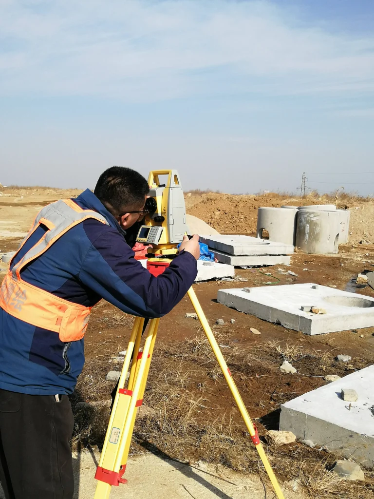
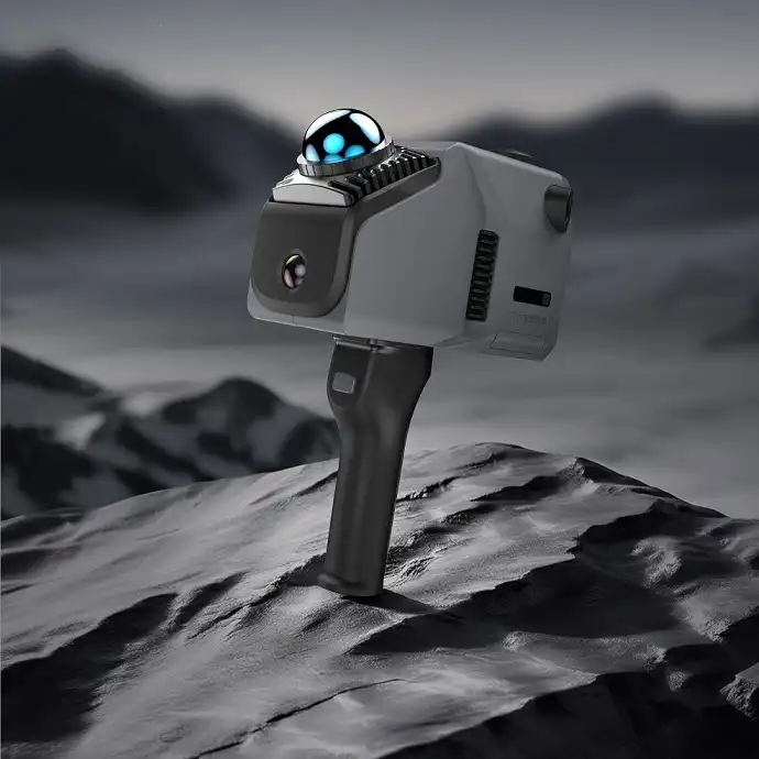
Ask any field inspector what limits their day, and the answer is usually the battery. Industrial handheld imagers – borescopes, thermal cameras and ultrasonic flaw detectors – are built for environments that consumer electronics never see: sub-zero start-ups on a construction site, hours of continuous scanning, vibration from generators and vehicles, and operators who cannot stop for a recharge in the middle of a pipeline survey. The battery pack is not an accessory bolted onto the device. It is the subsystem that sets the operating envelope, the duty cycle and, increasingly, the compliance status of the whole product.
Over more than a decade of designing custom packs for industrial handheld equipment, we have watched the same failure patterns repeat: packs that sag under load at low temperature, BMS decisions that fight the host firmware, enclosures that pass an IP test on paper but fail in rain, and certification surprises discovered weeks before launch. This article distils that experience into the engineering decisions that matter most when you specify or design a battery pack for a handheld imaging device.
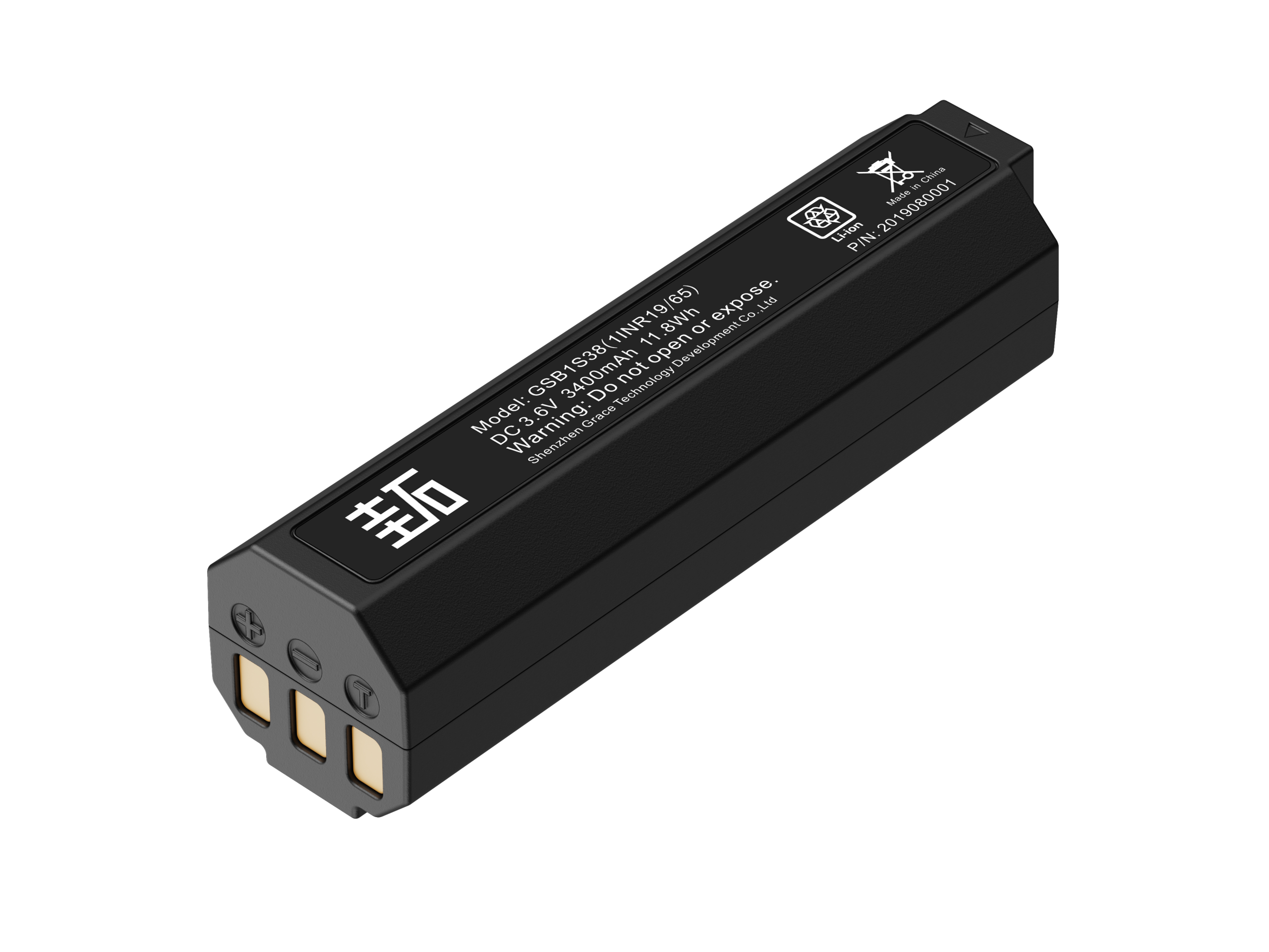
GSB1S38
3.6V/3450mAh/11.88Wh
Why the Battery Pack Decides the User Experience
A handheld imager is only as good as the energy it can carry. Runtime sets how many assets an inspector can check in a shift. Peak-current capability sets whether the device can capture the shot when it matters. Temperature behaviour sets whether the instrument works in the environment it was sold for. In our field-replacement analysis, battery-related failures are consistently among the top causes of warranty returns for portable inspection tools – rarely because the cells were defective, more often because the pack was not engineered for the real duty cycle.
This is why we treat the pack as a co-designed subsystem, not a commodity. The decisions that follow – chemistry, series configuration, BMS firmware, mechanical construction, certification strategy – are interdependent, and changing one late in the programme is expensive. The sections below walk through each decision in the order we make them, from load characterisation to release validation.
First, Understand the Load Profile
Every worthwhile pack design starts with the load, not the cell. The three dominant imager categories impose quite different demands, and a pack sized for the average power is often not the same design as one sized for the worst-case pulse. Table 1 summarises the patterns we see most often (order-of-magnitude reference values – always instrument your own prototype rather than relying on these).
Table 1. Typical load profiles and dominant design drivers for industrial handheld imagers (reference values).
| Device type | Typical load profile | Primary battery design driver |
| Industrial borescope | Continuous, moderate power (about 5-10 W) | Energy density and run time |
| Thermal imaging camera | Continuous capture with long idle phases (about 4-15 W) | Wide-temperature discharge and capacity |
| Ultrasonic flaw detector | Pulsed transmit-receive, high peak current (about 8-20 W average) | Peak-current capability and cycle life |
The pattern is consistent even when the numbers are not: imagers need hours of energy, bursts of current, and predictable performance across temperature. Quantify both the average discharge current and the pulse profile (amplitude, duration, frequency) before any cell is selected. In one project, a seemingly modest 2 A pulse every few seconds ruled out an otherwise attractive low-cost cell because its mid-pulse voltage sag dragged the input below the image sensor’s dropout threshold.
Cell Selection: Chemistry, Form Factor, and Supply Chain
Once the load profile is quantified, the cell choice follows. For handheld industrial imaging devices, cylindrical cells – 18650 and increasingly 21700 – dominate, for good reasons. The steel can provides mechanical rigidity that welded pouch cells struggle to match in a drop-prone tool. Cylindrical formats tolerate wide temperature swings with less swelling, and the supply chain, from tier-one cell makers to qualification data, is mature and auditable. Pouch cells still appear where thin form factors are non-negotiable, but they demand stricter swelling management and more careful integration.
Chemistry is where the real trade-offs live:
- NMC (nickel-manganese-cobalt) offers the highest energy density and is the right starting point when runtime is the headline specification. For an 18650 platform, 2.5-3.5 Ah NMC cells with a discharge window around -20 °C to +60 °C are a reasonable design basis to challenge, not to accept blindly.
- LFP (lithium iron phosphate) trades energy density for longer cycle life and better thermal stability. It suits devices that are charged daily in a fleet and where 2,000+ cycles matter more than the last 20% of runtime.
- LTO (lithium titanate) delivers true wide-temperature performance and fast charging, down to roughly -30 °C discharge, at a substantial energy penalty. We reserve it for specialty units where cold start and rapid turn-around outrank runtime.
We typically start a design review with NMC 18650s at 2.5-3.5 Ah in a 3S or 4S configuration, then challenge that assumption only when measured data – not intuition – demands a change. Qualification should include the maker’s datasheet, an independent discharge curve at your operating temperatures, and a short internal validation run before the design is frozen.
Pack Architecture and Capacity Engineering
Series count is set by the host device’s input voltage. A 12 V imaging platform commonly uses 3S, while higher bus voltages move to 4S; the choice also fixes the maximum pack voltage that the charger, host protection and certification paperwork must handle. Parallel count then sizes the capacity: required capacity is the product of average current and target runtime, divided by the usable-capacity derating you are willing to accept (a 15-20% reserve for end-of-life, temperature and load variation is typical). A 12 V device drawing 1.5 A average for an 8-hour shift needs roughly 12 Ah usable, which a 3S2P or 3S3P 18650 arrangement can approach.
Do not forget the energy-versus-power question. A pack with ample capacity can still fail if its continuous or pulse current rating is too low, because series cells stack voltage but not current capability. When pulses dominate, verify the cell’s pulse discharge curve at the operating temperature and keep busbar, fuse and connector ratings above the worst case. Finally, decide early whether the pack is swappable or sealed. Swappable packs add design freedom and hot-swap capability but force connectors, latching and spare-battery logistics. Sealed internal packs simplify ingress protection and compliance but make runtime a hard limit. In our experience, inspection tools sold for long shifts are better served by a swappable design with a charging cradle.
The BMS Is the Real Product
The cells are the engine; the BMS is the flight computer. A well-selected pack can still ship with a badly implemented BMS, and the field behaviour will show it. Four functions deserve most of the attention.
Protection and Safety Monitoring
Per-cell over-voltage, under-voltage, over-current, short-circuit and over-temperature protection must trip independently of host firmware, because the host can crash, hang or be powered down exactly when protection is needed. Protection thresholds and hysteresis should be specified numerically in the pack specification, then verified by test at the cell and pack levels. A hard-wired, self-latching protection path with a restart policy that the host can query is the pattern we standardise on.
State Estimation: SOC and SOH
Accurate state-of-charge (SOC) estimation matters far more in a field tool than in a consumer phone, because an inspector must trust the remaining-time number or plan a long walk around a wrong one. Coulomb counting with open-circuit-voltage correction and temperature compensation is the workhorse; model-based estimators add accuracy at the cost of more development effort. State-of-health (SOH) tracking lets the device warn of aging packs before they strand an operator.
Communication: SMBus and Smart Battery Data
A handheld imager is a natural fit for the Smart Battery System architecture: the pack reports voltage, current, temperature, remaining capacity and predicted runtime over a System Management Bus, and the host simply reads the data. The current SMBus specification (Version 3.3.1) and the associated Smart Battery Data registers define the command set [5]. Defining these registers together with the host firmware team – before firmware is written – prevents the classic integration failure where each side believes the other owns battery intelligence.
Cell Balancing
Passive balancing at the top of charge is sufficient for most 3S-4S packs if cells are well matched at assembly and the balancing window is generous. Aggressive balancing strategies add cost and heat for little field benefit unless the pack is used with widely varying partial charges. Whatever the strategy, specify it and measure imbalance drift during validation.
Thermal Design for Wide-Temperature Field Operation
Industrial imagers are frequently rated for -20 °C to +60 °C ambient operation, and the battery is often the weakest link in that envelope. Lithium-ion cells discharge acceptably over a wide window (roughly -20 °C to +60 °C is a common design basis), but at low temperature internal resistance rises sharply: peak current capability drops, voltage sags under load, and available capacity shrinks. Charge is far more restricted – charging below about 0 °C risks lithium plating and permanent capacity loss, so the BMS must either block charging outside the allowed window or engage heating first.
Two design measures pay for themselves. First, place temperature sensors at the cells, not only on the PCB, and log temperature alongside voltage during validation. Second, for genuinely cold environments, include a low-power heater or charge-enable hysteresis so the pack can warm itself before accepting charge. We learned this the hard way on a pipeline-inspection project: packs returned from winter sites showed capacity fade that traced directly to charge events at negative temperatures, a failure invisible in a lab that only tested at 25 °C.
There is also a subtler thermal constraint specific to imaging: self-heating. A thermal camera is only as good as its thermal reference, and a hot battery bolted to the enclosure can corrupt the measurement. Where the sensor sits close to the pack, add thermal isolation, minimise heat paths, and verify with the device powered and charging simultaneously – the worst case is rarely the one you first think of.
Mechanical Ruggedness: Vibration, Shock, and Ingress Protection
Handheld tools live a violent life: dropped onto concrete, strapped to vibrating machinery, carried through rain and dust. The pack must survive all of it without intermittent contacts or cell damage. Three standards frame the requirement. Sinusoidal vibration per IEC 60068-2-6 and shock per IEC 60068-2-27 are the common environmental tests we apply at pack level [7][8]. Ingress protection is specified by the IP code per IEC 60529 [6]; for field inspection tools IP54 and above is typical, and the battery compartment, connector and vent path all have to be designed for it, not just the housing.
Mechanical robustness is earned in small details: cells held by rigid carriers or structural adhesive, inter-cell foam to absorb shock, welded busbars with adequate cross-section, connector latching with strain relief on cables, and potting or conformal coating where the BMS PCB must survive condensation. In a vibration test that a customer ran on our reference design, the failure mode was not the cells – it was the connector that slowly unlatched under 2 g of random vibration. Connector selection and locking belong in the pack specification from day one.
Charging Strategy and Calendar Life
Charging is where battery life is won or lost. The standard profile is constant-current / constant-voltage (CC-CV): charge at a moderate current (around 0.5C is a sensible default for field packs) to the top voltage, then hold voltage while current tapers to a termination threshold (commonly C/20). Faster charging shortens charge time but increases heat and accelerates aging; for a pack charged overnight or during a shift break, 0.5C is almost always the right trade-off.
Calendar life deserves as much attention as cycle life, because most field batteries spend most of their life idle. Storage at high state of charge and high temperature is the fastest way to age a pack. Our guidance to customers is consistent: store at 30-50% SOC in moderate temperatures, and let the charger communicate the ideal storage target through the SMBus data rather than leaving it to chance. These are practical engineering defaults, not product specifications – the exact numbers should come from your cell maker’s aging data at your operating temperatures.
Certification and Transport Compliance
Certification is a go-to-market gate, and it is cheaper to plan than to rescue. Table 2 lists the standards that appear in most programmes for industrial handheld imaging packs. The baseline cell and pack safety standard for portable sealed lithium systems is IEC 62133-2 (current consolidated version includes Amendment 1) [1]. UL 1642 and UL 2054 are frequently referenced for North American component and battery acceptance [2][3]. Where the host instrument falls under IEC 61010-1 for measurement and control equipment, the battery interface must be assessed as part of the whole product [9].
Table 2. Certification and transport compliance matrix commonly applied to industrial handheld imager battery packs.
| Certification / standard | Scope | Why it matters for imager packs |
| IEC 62133-2:2017+A1:2021 [1] | Safety requirements for portable sealed lithium cells and batteries | Baseline cell and pack safety; accepted in most market entries |
| UL 1642, Edition 6 [2] | Lithium cell safety | Common component-level acceptance in North America |
| UL 2054, Third Edition [3] | Household and commercial battery safety | Pack-level safety where UL 2054 is referenced |
| UN 38.3, Rev. 8 Amend. 1 [4] | Transport tests T1-T8 for lithium batteries | Mandatory for shipping cells or packs by any mode |
| IEC 61010-1:2010+A1:2016 [9] | Safety of electrical equipment for measurement and control | Applies to the host instrument; battery interface must comply |
Transport compliance is where many programmes stumble. UN 38.3 requires eight tests on each cell or battery type – altitude simulation, thermal, vibration, shock, external short circuit, impact or crush, overcharge and forced discharge – before the product may be shipped by any mode [4]. Air carriers generally require lithium-ion batteries to be shipped at or below 30% state of charge, and classification, packaging instructions and quantity limits differ between air, sea and road (IATA DGR, IMDG Code and ADR). These rules are revised regularly, so confirm against the editions in force at the actual shipment date rather than assuming a fixed limit. Certification samples must be representative of production; testing a hand-built prototype and shipping a different production design is a classic and expensive mistake.
Reliability Validation: What We Test Before Field Release
A release decision should be made on data, not on calendar time. Our validation plan for an imager pack covers four fronts. First, cell qualification: discharge curves at the operating temperature extremes, internal resistance, and a short accelerated-aging sample. Second, pack-level environmental testing: vibration and shock per IEC 60068 [7][8], thermal shock across the full temperature range, and IP ingress checks on the final sealing design. Third, electrical behaviour: protection trip points, SMBus register accuracy against a reference meter, and charge-termination behaviour at temperature limits. Fourth, field simulation: representative charge-discharge cycling, storage at the recommended SOC, and the pulse profile captured from the real device.
Every failure found in validation must be closed with a root-cause analysis and a documented design change – not filed as an anomaly. In one thermal-camera programme, early validation showed the SOC drift growing after repeated partial charges. The fix was not in the cells but in the SOC algorithm, which was re-baselined at the top of charge. That finding would never have surfaced without a field-representative cycle profile. Plan the validation schedule to match the certification timeline; UN 38.3 samples, safety certification samples and DVT units are not interchangeable.
An Engineer’s Checklist for Your Next Imager Battery
- Instrument the real prototype: measure average current, pulse profile, and temperature for a full field day before choosing cells.
- Size capacity for the runtime target, applying a 15-20% usable-capacity derating for end-of-life and cold operation.
- Select chemistry and form factor on mechanical, thermal and supply-chain evidence, not on the datasheet headline.
- Decide series count, parallel count, and swappable-versus-sealed early – they drive connector, housing and compliance work.
- Specify BMS protection thresholds numerically and define SMBus / Smart Battery Data registers with the host team before firmware.
- Set charge temperature windows and storage SOC guidance, and make them visible through the charger and host UI.
- Put vibration, shock and IP requirements into the pack-level specification (IEC 60068-2-6, IEC 60068-2-27, IEC 60529).
- Schedule UN 38.3, safety certification and transport documentation into the programme plan, with production-representative samples.
- Run a formal design-validation plan and close every failure with root-cause analysis before release.
Conclusion
The battery pack is the subsystem that decides whether a handheld imager works in the field or fails when it matters. The path to a reliable design is not mysterious: characterise the load with real data, select cells and chemistry on evidence, treat the BMS as a product in its own right, engineer for the temperature and mechanical reality of the field, and plan certification from day one. Done in that order, the pack stops being a warranty risk and becomes a genuine differentiator – runtime, cold-weather reliability and trustworthy state information are features that operators notice on every shift.
The standards referenced in this article are all current at the time of writing; always verify the latest editions with the issuing bodies before committing a programme to a specific revision.
References
[1] IEC 62133-2:2017+AMD1:2021 CSV, Secondary cells and batteries containing alkaline or other non-acid electrolytes – Safety requirements for portable sealed secondary cells, and for batteries made from them, for use in portable applications – Part 2: Lithium systems. International Electrotechnical Commission. https://webstore.iec.ch/en/publication/70017
[2] UL 1642, Standard for Lithium Batteries, Edition 6 (2020), last revision October 2022. UL Standards & Engagement. https://shopulstandards.com/ProductDetail.aspx?productId=UL1642_6_S_20200929
[3] UL 2054, Standard for Household and Commercial Batteries, Third Edition (November 2021). UL Standards & Engagement (recognized consensus standard, U.S. FDA).
[4] UN Manual of Tests and Criteria, Eighth Revised Edition, Amendment 1 (2025), Part III, Subsection 38.3. United Nations Economic Commission for Europe. https://unece.org/sites/default/files/2026-01/ST-SG-AC10-11-Rev8-Amend1C_0.pdf
[5] System Management Bus (SMBus) Specification, Version 3.3.1 (20 October 2024). System Management Interface Forum. https://smbus.org/specs/spec_content.htm
[6] IEC 60529, Degrees of protection provided by enclosures (IP Code), Edition 2.2 (1989 + AMD1:1999 + AMD2:2013, including 2019 corrigendum). International Electrotechnical Commission. https://webstore.iec.ch/publication/2452
[7] IEC 60068-2-6:2007, Environmental testing – Part 2-6: Tests – Test Fc: Vibration (sinusoidal), Edition 7.0. International Electrotechnical Commission. https://webstore.iec.ch/en/publication/544
[8] IEC 60068-2-27:2008, Environmental testing – Part 2-27: Tests – Test Ea and guidance: Shock, Edition 4.0. International Electrotechnical Commission. https://webstore.iec.ch/en/publication/514
[9] IEC 61010-1:2010+A1:2016, Safety requirements for electrical equipment for measurement, control, and laboratory use – Part 1: General requirements, Edition 3.1. International Electrotechnical Commission / ANSI Webstore. https://webstore.ansi.org/standards/iec/iec61010ed2017