By a Lithium Battery Engineer, Medical Device Programs | TEFOO
For a patient monitor in an intensive care unit, a pulse oximeter on a ward, a point-of-care ultrasound in an emergency room, or an infusion pump moving between beds, the battery is not an accessory—it is part of the measurement chain. I lead battery engineering for medical device programs at TEFOO, where our team designs smart lithium battery systems for diagnostic and therapeutic device OEMs worldwide. In this article I want to share, from the engineer’s seat, what separates a properly engineered custom battery pack for a medical diagnostic device from a generic lithium pack, and how to specify one.
The short version: a diagnostic device battery is a measurement-integrity system. It must keep the instrument’s essential performance intact, survive single-fault conditions, communicate its state honestly, and remain traceable for years after shipment. The sections below walk through the engineering decisions behind each of those requirements.
1. Why a Diagnostic Device Battery Is a Measurement-Integrity System
In consumer electronics, a battery failure is an inconvenience; in a diagnostic device, it can mean an interrupted measurement, a lost trend, or a reading the clinician cannot trust. Medical electrical equipment is evaluated against IEC 60601-1 [1], which holds the device to basic safety and essential performance, including behavior under single-fault conditions. If the battery cannot carry the essential performance of monitoring or measurement when mains power disappears, the design has failed its primary duty.
This changes the design philosophy at every layer. Cell selection is chosen for controlled failure modes rather than maximum energy. The battery management system (BMS) is built for fail-safe behavior rather than convenience. And every unit is traceable to its build batch, test records, and firmware version—because when an OEM files a device registration, regulators will ask for exactly that evidence.
2. The Diagnostic Device Landscape: One Battery Does Not Fit All
One of the most common mistakes I see in battery procurement is asking for “a battery for a medical device” as if one specification fits every instrument. It does not. A bedside patient monitor, a handheld pulse oximeter, a point-of-care ultrasound scanner, and an infusion pump impose fundamentally different duty cycles on the battery.
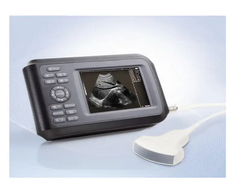
Bedside monitors run from AC mains with the battery as backup, typically sized to carry the monitor through a power outage or an intra-hospital transfer. Transport and portable monitors may run from the battery for whole shifts, often in vehicles or uncontrolled environments. Handheld diagnostics such as pulse oximeters and glucose meters draw small average power but demand years of shelf life, long standby, and honest low-battery warnings. Point-of-care ultrasound combines high peak-current pulses with the need to stay compact and cool. Infusion pumps must keep pumping on battery for extended periods and report remaining runtime reliably. Home-use diagnostics add the environment defined in IEC 60601-1-11 [3], where untrained users and casual handling must not defeat the design.
Device-specific particular standards matter as much as the general one. A multifunction patient monitor is assessed against IEC 80601-2-49 [11], and an electrocardiograph against IEC 60601-2-25 [12]—each with its own expectations for essential performance and alarm behavior. The battery engineering must support the device standard, not the other way around.
Table 1. Diagnostic Device Classes and Their Battery Requirements
| Device class | Power role | Typical runtime target | Environment | Key battery priority |
| Bedside patient monitor | Backup during mains failure and transfer | On the order of 1–4 h, product-dependent | Climate-controlled ward | Energy density, quiet operation, honest SOC |
| Portable / transport monitor | Often the primary source for a shift | Multi-hour; hot-swap desirable | Wards, vehicles, uncontrolled temperature | Ruggedness, predictable runtime, SMBus data |
| Handheld diagnostics (SpO₂, glucose) | Primary source; long standby | Years of shelf life plus long run time | Pocket, home, bedside | Low self-discharge, small form factor, low-battery honesty |
| Point-of-care ultrasound | Primary source, high peak pulses | On the order of 1–2 h scanning, product-dependent | Emergency, ward, field use | Peak-current delivery, thermal stability, compactness |
| Infusion pump | Primary/backup; uninterrupted pumping | Extended runtime at defined flow rates | Ward, home, ambulance | Reliable remaining-time reporting, cycling life |
| Home-use diagnostics | Primary source; lay users | Product-dependent | Home healthcare environment (IEC 60601-1-11) | Fool-proof charging, clear warnings, safety |
The takeaway: specify the battery from the duty cycle, not from the device name. Ask first where the instrument will be used, what the longest uninterrupted period it must survive actually is, and what the device standard expects of the power source.
3. Cell Chemistry Selection for Diagnostic Instruments
Chemistry is where safety is decided before the pack is even assembled. For diagnostic programs we work with two families of lithium-ion cells, and we qualify both against IEC 62133-2:2017+A1:2021 [5].
Nickel-manganese-cobalt (NMC) cells offer the highest energy density, which matters in a bedside monitor where the battery lives inside a tight enclosure and must provide meaningful backup without stealing space from the electronics. The trade-off is that NMC requires disciplined thermal management and a robust BMS, because energy density and failure energy scale together.
Lithium iron phosphate (LFP) cells trade some energy density for significantly better thermal stability, longer cycle life, and a wider operating temperature window. For packs that sit at high state of charge for long periods—as infusion pumps and portable monitors often do—or cycle frequently, LFP is frequently the better engineering choice.
Two rules govern our cell selection process. First, the cell must carry IEC 62133-2 certification from its manufacturer, and we audit batch consistency and traceability; cells are the one component we do not substitute casually. Second, we characterize the load itself: diagnostics are rarely a constant resistive load. Ultrasound scanning draws high current pulses, defibrillation-ready instruments demand voltage that holds across transients, and even a simple oximeter has a duty cycle that shapes the discharge profile. The pack must hold its voltage and its measurement integrity across the full envelope.
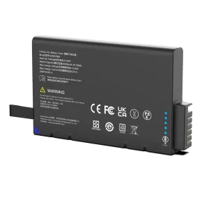
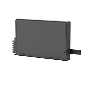
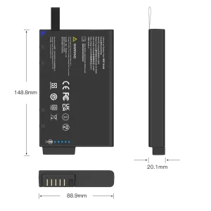
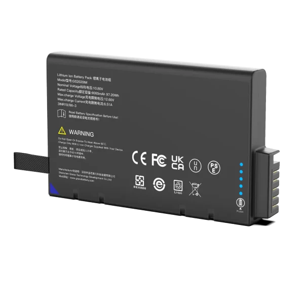
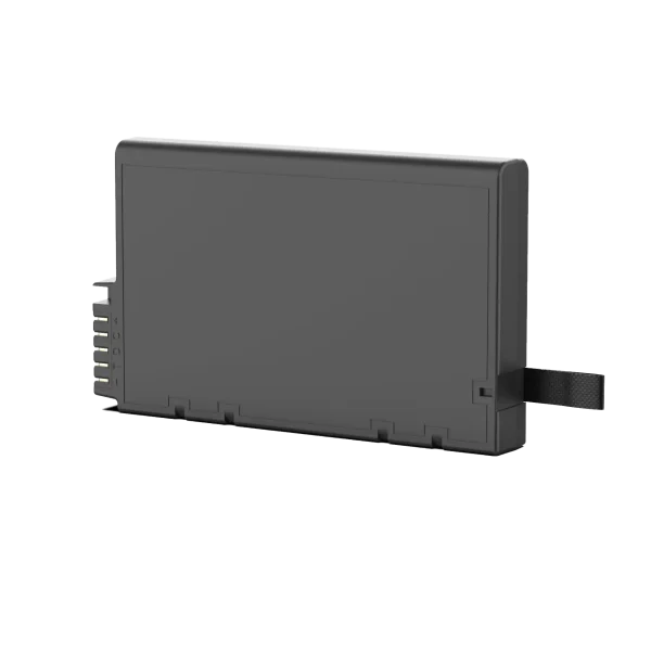
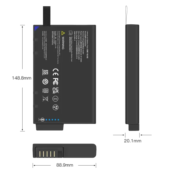
GS2020IM
10.8V/9300mAh/97.2Wh
4. Electrical Architecture: The Smart Battery (BMS + SMBus)
Capacity planning starts from the load envelope. We multiply the device’s power profile by the target runtime, then add margins for aging and temperature: a pack that ends its useful life at roughly 80% of initial state of health (SOH) must still meet the runtime specification. The result determines the nominal capacity and the series/parallel configuration.
The battery management system is the intelligence of the pack. It performs state-of-charge (SOC) and state-of-health estimation, balances cells, and enforces over-voltage, under-voltage, over-current, and over-temperature limits—with a second protection layer, such as a chemical fuse or secondary protector, that acts independently of the primary electronics.
Where TEFOO adds particular value is the communication layer. Diagnostic devices increasingly use the SMBus and the Smart Battery Data Specification [15][16] so the host can read RemainingCapacity, RunTimeToEmpty, RelativeStateOfCharge, DesignCapacity, and cycle count in real time. For a clinician this is not a luxury: the difference between a battery that reports honest remaining time and one that does not can change operational decisions—whether to move a patient, start a procedure, or change a pack. The smart-battery interface also lets the device escalate alarms as the battery crosses defined thresholds.
Charging is designed, not assumed. We implement CC-CV profiles with temperature-windowed control: charging is inhibited below the cell’s low-temperature threshold, because charging a cold lithium cell is a well-understood hazard, and charge current is derated at high temperature. For home-use devices, charging behavior must also be fool-proof for lay users under IEC 60601-1-11 [3] and usability engineering under IEC 62366-1 [9].
5. EMC and Signal Integrity: Batteries Inside Measurement Devices
A diagnostic device measures signals that can be very small—an ECG lead is measured in millivolts, a pulse oximeter’s plethysmographic signal in a similar range—and a battery that injects noise into that measurement is a clinical problem, not just an engineering one. IEC 60601-1-2 [2] sets the electromagnetic compatibility requirements, and the battery subsystem must neither disturb the instrument nor be disturbed by it.
In practice this drives real design work: switching regulators on the BMS are placed and filtered so their ripple does not couple into the analog front end; grounding and shielding are planned so power return paths do not share the measurement reference; and immunity to electrostatic discharge and radiated fields is validated at the pack level, not assumed from a component datasheet. In one monitoring program, early prototypes showed a faint ripple artifact on the ECG trace during battery discharge; we traced it to the boost converter’s switching frequency, moved the converter, added a pi filter, and re-validated. The trace was clean afterwards—but only because we tested on the real device.
Usability belongs in the same conversation. Under IEC 62366-1 [9], battery-related information—remaining runtime, low-battery warnings, end-of-life behavior—must be understandable to the intended user, including a layperson at home. A battery indicator that silently goes dark is not just a nuisance; it is a usability failure.
6. Mechanical, Thermal and Environmental Design
A portable diagnostic pack is a mechanical component as much as an electrical one. The home healthcare environment in IEC 60601-1-11 [3] and the emergency medical services environment in IEC 60601-1-12 [4] define conditions that include drops, vibration, temperature swings, humidity, and altitude changes. The pack structure, cell interconnection and welding process, connector strain relief, and mounting all have to be engineered and tested for these conditions—not assumed.
Thermal design deserves its own paragraph. A pack charging in a closed vehicle cabin on a summer day, or an ultrasound probe left on a sunny cart, can see ambient temperatures far outside the comfort range. Our designs include thermally conductive paths, charge-temperature limits, and, where needed, passive insulation to keep cells within their rated window. Cold is handled too: charging below the cell’s low-temperature threshold is inhibited by firmware, and discharge performance is derated predictably so the device can report honest runtime in the cold.
Practical details matter as much as analysis: keyed connectors that cannot be inserted incorrectly, locking mechanisms that survive vibration, hot-swap contacts rated for repeated mating cycles, and an enclosure that meets the device’s ingress-protection requirements. These are the details that separate a pack that works in the field from one that only works in the lab.
7. Safety and Compliance Roadmap
Compliance is a program, not a certificate. For a diagnostic device battery program we maintain a standards map covering the battery as a component and the instrument as a finished medical device. Table 2 summarizes the standards that appear in essentially every program we work on.
Table 2. Compliance Roadmap for a Diagnostic Device Battery Program
| Standard | Scope | What it means for the battery |
| IEC 60601-1 (Ed 3.2) [1] | Basic safety and essential performance; single-fault conditions | Battery must not create single-fault hazards; isolation, enclosure, markings |
| IEC 60601-1-2 (Ed 4.1) [2] | Electromagnetic compatibility | Battery electronics must neither disturb measurement nor be disturbed by it |
| IEC 60601-1-11 (Ed 2.1) [3] | Home healthcare environment | Lay-user safety, fool-proof charging, clear warnings |
| IEC 60601-1-12 (Ed 1.1) [4] | Emergency medical services environment | Temperature, humidity, altitude and vibration profiles for field use |
| IEC 62133-2:2017+A1:2021 [5] | Portable sealed lithium cells and batteries | Cell- and pack-level safety tests: overcharge, short circuit, thermal |
| ISO 13485:2016 [6] | Quality management for medical devices | Design control, risk management and traceability across the lifecycle |
| ISO 14971:2019 [7] | Risk management for medical devices | Hazard analysis and risk controls applied to the battery subsystem |
| UN 38.3 (Rev. 8) [8] | Transport of lithium batteries | T1–T8 tests required for air, sea and road transport |
| IEC 62366-1 (Ed 1.1) [9] | Usability engineering for medical devices | Battery indicators and warnings must be understandable by the intended user |
| UL 2054 [10] | Household and commercial batteries (North America) | Additional pack-level safety evaluation for the US market |
| RoHS / REACH [13][14] | Hazardous substances in EEE; chemicals regulation (EU) | Restricted-substance compliance and chemical documentation |
A practical clarification that saves OEMs time: the battery pack is a component. Component-level tests—IEC 62133-2 safety [5], UN 38.3 transport testing [8], and environmental and EMC tests at the pack level—are our responsibility, and we document them completely. Certification of the finished device under IEC 60601-1 [1] and its collateral and particular standards is the OEM’s responsibility, and we support it with design documentation, test reports, and traceability records. A battery vendor that promises to “certify your device” is overpromising; a vendor that hands you clean component-level evidence is the one you want.
8. Validation We Run Before Shipping
Every production batch at TEFOO goes through formation, capacity grading, internal-resistance and open-circuit-voltage checks, and SOC calibration. Beyond that, our qualification programs run cycle-life tests to the OEM’s defined end of life, high- and low-temperature storage, vibration, shock and drop tests, over-charge, over-discharge and short-circuit abuse tests, fault injection on the BMS, and EMC testing at the component level.
Real-world lessons are where this investment pays off. In one monitoring program, early prototypes showed SOC drift after repeated exposure to cabin temperatures above 50 °C; we traced it to the impedance model and added temperature compensation plus periodic recalibration. In another, hot-swap testing revealed that the first connector candidate could not handle the number of mating cycles a ward performs in a year, so we replaced it with a higher-durability contact. And as described above, an EMC issue that only appeared on the real device forced a converter layout change. None of these would have surfaced in a datasheet review; all of them surfaced because we test the way the product is used.
Traceability closes the loop. Every pack carries a unique serial number tied to its cell batches, firmware version, test results and design history file, so the OEM can answer any regulatory question about a specific unit years after shipment.
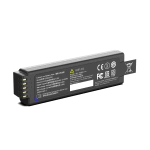
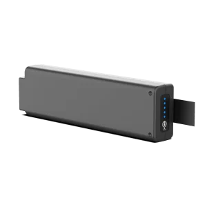
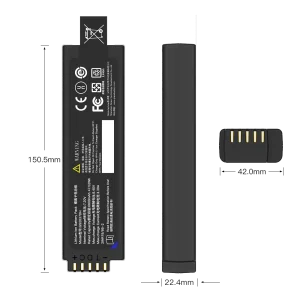
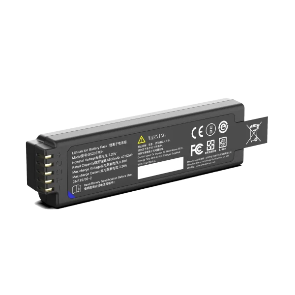
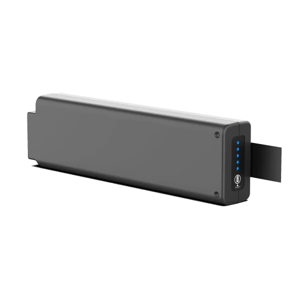
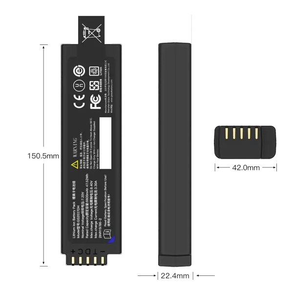
GS2037DH
7.2V/6900mAh/47.52Wh
9. How TEFOO Customizes a Diagnostic Device Battery Pack
Custom battery development follows a five-stage process at TEFOO:
Specification—we work with your engineers to freeze the load envelope, runtime target, mechanical interface, connector, communication protocol, and the standards list for your target markets. Design—cell topology, BMS hardware and firmware, thermal and mechanical design, with a DFMEA reviewed jointly with your team. Prototype—functional prototypes that run on your device or a load simulator, with design verification tests. Validation—internal qualification plus third-party testing where required, with full reports. Production—controlled manufacturing with 100% functional test, batch records, and serial-level traceability.
To start, the most useful things you can bring are the device’s measured power envelope, the target runtime, the mechanical and electrical interface drawings, the charging profile your instrument will use, and the list of markets you plan to register in. With those, we can usually return a preliminary specification and risk review within a short feasibility study.
TEFOO’s engineering team lives in smart battery systems—intelligent BMS, SMBus communication, and OEM customization—and our quality system is built on the discipline of ISO 13485 [6], including design control and risk management across the product lifecycle.
10. Closing Thoughts
A custom battery pack for a medical diagnostic device is not a box of cells with a label. It is a safety system, a measurement-integrity component and a data source, engineered around a specific duty cycle and validated for a specific environment. Done properly, it disappears into the product and does its job for years; done casually, it becomes the weakest link between the patient and the diagnosis.
If you are specifying a battery program for a diagnostic device, we would be glad to review your requirements. Contact the TEFOO engineering team, and we will start from your load envelope and duty cycle—not from a catalogue.
References
[1] IEC 60601-1:2005+AMD1:2012+AMD2:2020 CSV (Ed 3.2), Medical electrical equipment – Part 1: General requirements for basic safety and essential performance. IEC Webstore. https://webstore.iec.ch/en/publication/67497
[2] IEC 60601-1-2:2014+AMD1:2020 CSV (Ed 4.1), Medical electrical equipment – Part 1-2: Collateral Standard: Electromagnetic disturbances – Requirements and tests. IEC Webstore. https://webstore.iec.ch/publication/67554
[3] IEC 60601-1-11:2015+AMD1:2020 CSV (Ed 2.1), Medical electrical equipment – Part 1-11: Collateral Standard: Requirements for ME equipment and ME systems used in the home healthcare environment. IEC Webstore. https://webstore.iec.ch/en/publication/67384
[4] IEC 60601-1-12:2014+AMD1:2020 CSV (Ed 1.1), Medical electrical equipment – Part 1-12: Collateral Standard: Requirements for ME equipment and ME systems intended for use in the emergency medical services environment. IEC Webstore. https://webstore.iec.ch/en/publication/67385
[5] IEC 62133-2:2017+AMD1:2021 CSV (Ed 1.1), Secondary cells and batteries containing alkaline or other non-acid electrolytes – Safety requirements for portable sealed secondary cells, and for batteries made from them, for use in portable applications – Part 2: Lithium systems. IEC Webstore. https://webstore.iec.ch/en/publication/70017
[6] ISO 13485:2016, Medical devices – Quality management systems – Requirements for regulatory purposes. ISO. https://www.iso.org/standard/59752.html
[7] ISO 14971:2019, Medical devices – Application of risk management to medical devices. ISO. https://www.iso.org/obp/ui/#iso:std:iso:14971:en
[8] United Nations, Recommendations on the Transport of Dangerous Goods: Manual of Tests and Criteria, Eighth revised edition and Amendment 1, Section 38.3 (ST/SG/AC.10/11/Rev.8). UNECE. https://unece.org/transport/dangerous-goods/rev8-files
[9] IEC 62366-1:2015+AMD1:2020 CSV (Ed 1.1), Medical devices – Part 1: Application of usability engineering to medical devices. IEC Webstore. https://webstore.iec.ch/publication/67220
[10] UL 2054, Household and Commercial Batteries (2nd Edition). UL Solutions. https://www.ulsolutions.com.cn/industries/batteries-and-components/batteries/battery-safety-testing
[11] IEC 80601-2-49:2018+AMD1:2024 CSV, Medical electrical equipment – Part 2-49: Particular requirements for the basic safety and essential performance of multifunction patient monitors. IEC Webstore. https://webstore.iec.ch/en/publication/100456
[12] IEC 60601-2-25:2011 (Ed 2.0), Medical electrical equipment – Part 2-25: Particular requirements for the basic safety and essential performance of electrocardiographs. IEC Webstore. https://webstore.iec.ch/en/publication/2636
[13] Directive 2011/65/EU of the European Parliament and of the Council on the restriction of the use of certain hazardous substances in electrical and electronic equipment (RoHS), consolidated text. EUR-Lex. https://eur-lex.europa.eu/legal-content/EN/TXT/HTML/?uri=CELEX%3A02011L0065-20240801
[14] Regulation (EC) No 1907/2006 of the European Parliament and of the Council concerning the Registration, Evaluation, Authorisation and Restriction of Chemicals (REACH), consolidated text. EUR-Lex. https://eur-lex.europa.eu/legal-content/EN/TXT/PDF/?uri=CELEX:02006R1907-20241010
[15] Smart Battery Data Specification, Revision 1.1. Smart Battery System Implementers Forum (SBS-IF). https://sbs-forum.org/specs/
[16] System Management Bus (SMBus) Specification, Version 3.3. SBS Implementers Forum. https://www.smbus.org/specs/SMBus_3_3_20240512.pdf