What a battery engineer wants OEMs to know before specifying the power source for point-of-care imaging
By a Senior R&D Engineer, Battery Systems – TEFOO (Shenzhen, China) | October 2026
Every portable ultrasound system has two imaging engines: the transducer and the battery. The first is optimised by the device team for image quality; the second is too often treated as a commodity accessory, and only rediscovered when a scan is interrupted in the middle of a procedure. Written from the perspective of a lithium battery R&D engineer who designs packs for medical equipment, this article walks through how a portable ultrasound actually consumes power, how we select cells and build the pack, which safety and quality standards govern the design, and how an OEM should specify and validate the battery before it reaches the field.
Why the battery deserves engineering attention
Point-of-care and portable ultrasound has moved imaging out of the radiology suite and into emergency rooms, intensive care units, operating theatres, ambulances, primary-care clinics and field medicine. In those environments the battery is not a convenience; it is the difference between a completed exam and an aborted one. A 15-minute charge, or a battery that reports 40 % and drops to 5 % within two scans, erodes clinical confidence in the whole device.
There is also a regulatory dimension. In the European Union and the United States, the battery is part of a medical electrical (ME) device. Its safety, the quality system that produced it, its electromagnetic behaviour and even the way it is transported are all governed by standards and regulations that apply to the complete system. The battery must therefore be designed, tested and documented with the same discipline as the imaging electronics.
Model the load before you pick the cells
Battery engineering starts with a power budget, not with a cell catalogue. A portable ultrasound has several load groups with very different characteristics: the transducer front-end and beamforming electronics that excite the array and receive echoes; the image-processing and display subsystem; connectivity such as Wi-Fi, USB and peripherals; and the idle, freeze and standby states that dominate a typical clinical day.
Published figures from real devices give a useful sense of scale. One pocket-sized ultrasound system specifies a built-in 2200 mAh battery, roughly 3 W live operation, roughly 1 W in freeze, about 4 hours of continuous scanning and about 72 hours of standby[10]. A wireless handheld transducer specifies a 1650 mAh built-in cell at 3.85 V, with a 3000 mAh wireless capsule at 3.6 V[11] to recharge it on the go. Across the industry, portable systems are commonly quoted at 2 to 8 hours of continuous operation[9] depending on imaging mode and system power consumption.
The point is that the load is defined by the clinical workflow: scan bursts of one to ten minutes, longer idle periods, and occasional peak loads when saving images or streaming. The battery must sustain the worst realistic duty cycle, not the datasheet best case. Measure the system’s current profile in every mode before fixing the capacity target. Table 1 shows an illustrative power budget for a mid-size cart-portable system; treat the numbers as a template and replace them with your own measurements.
Table 1 – Illustrative power budget for a mid-size portable ultrasound (design example; replace with measured values)
| Subsystem | Average draw (W) | Notes |
| Transducer front-end & beamforming | 6 | Scales with channel count and frame rate |
| Image processing / CPU | 4 | 2D and Doppler modes dominate |
| Display | 3 | Backlight is a major variable |
| Connectivity (Wi-Fi / USB / peripherals) | 1 | Bursts during export and streaming |
| Idle / freeze | 1 | Screen on, acquisition paused |
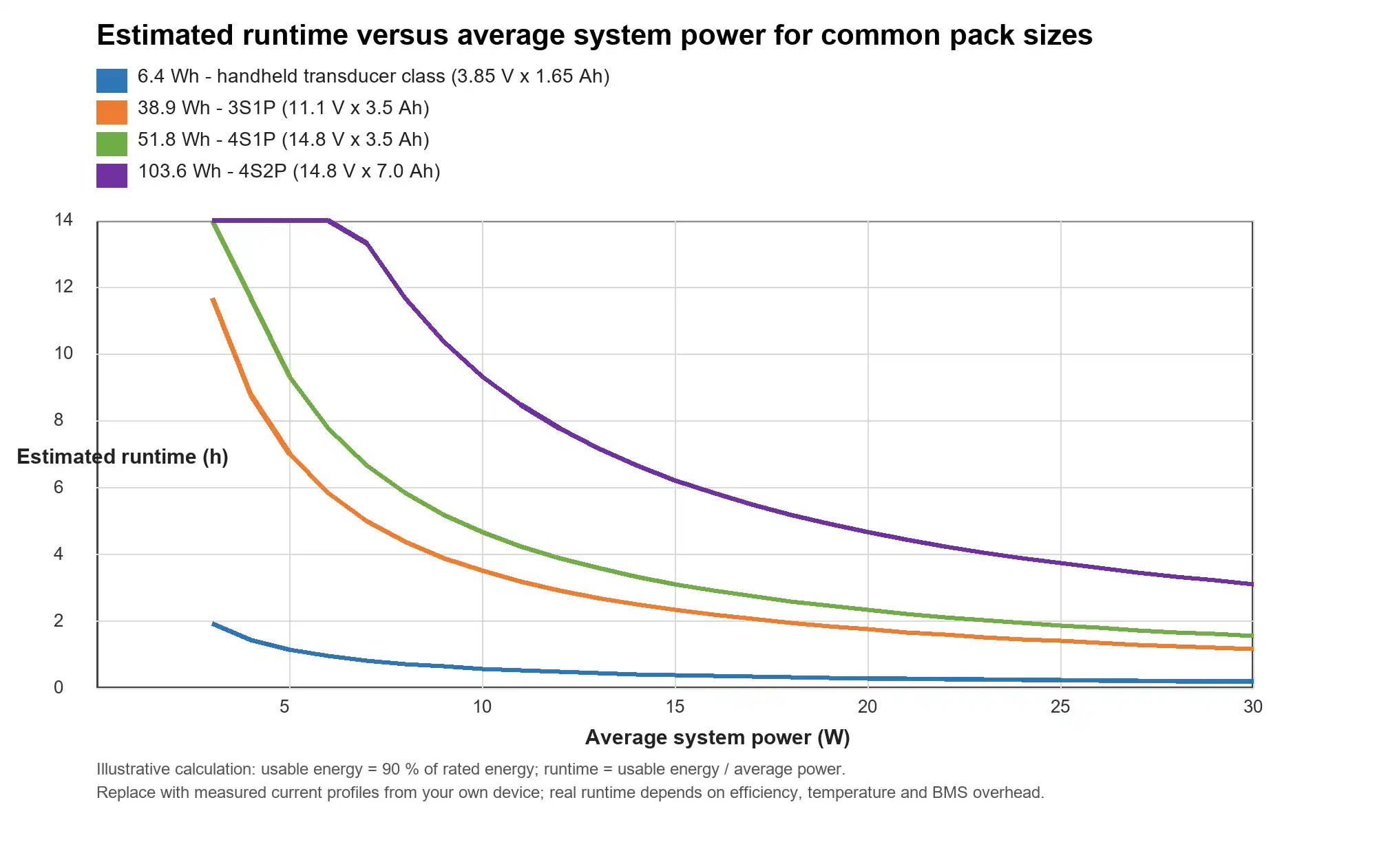
Figure 1 translates capacity into clinical time. The curves assume that 90 % of the rated energy is usable, a realistic planning value that already accounts for charge cut-off, discharge cut-off and BMS overhead. A 6.4 Wh handheld-class pack is measured in tens of minutes; a 103.6 Wh cart-portable pack buys a full clinic day. Picking the pack size is therefore a clinical decision (how long must a full day run without a mains socket?) expressed in watt-hours.
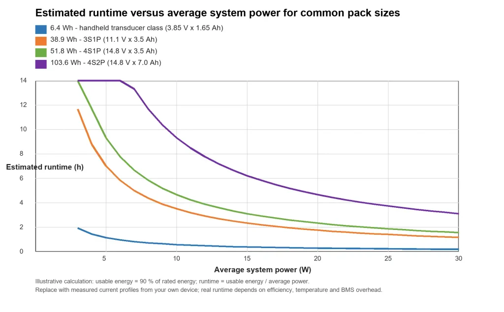
Figure 1 – Estimated runtime versus average system power for common pack sizes (illustrative calculation, 90 % usable energy).
Cell chemistry: NMC remains the workhorse
For most portable ultrasound packs, NMC (nickel-manganese-cobalt) chemistry is the right default, and the reasons are quantitative rather than fashionable. First, energy density: current commercial NMC cells typically reach around 240-270 Wh/kg at cell level, whereas LFP (lithium iron phosphate) typically sits near 160-190 Wh/kg. In a handheld device, every 100 g of battery is a compromise on ergonomics and probe balance; the higher density of NMC directly buys runtime or weight.
Second, state-of-charge (SoC) estimation. NMC has a sloping open-circuit voltage curve, which makes fuel gauging more accurate across the full range. LFP’s very flat voltage plateau is a well-known problem for percentage-display accuracy, exactly the complaint that erodes user trust when a device jumps from 30 % to 10 %. Third, the duty cycle fits: ultrasound scans are short-burst, moderate-rate loads, not continuous high-rate discharge, so NMC’s cycle life (typically several hundred to roughly 800 cycles to 80 % capacity at moderate depth of discharge) is entirely adequate for a medical device that is replaced or refurbished on a defined lifecycle.
That is not a blanket rejection of LFP. For high-cycle, high-scan-hour cart systems where weight is less critical and cycle life dominates, LFP can be the better engineering answer. The lesson is to let the load profile and clinical duty cycle drive the chemistry choice, and to confirm every figure against the cell supplier’s datasheet before committing.
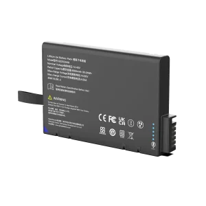
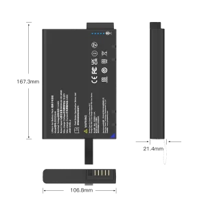
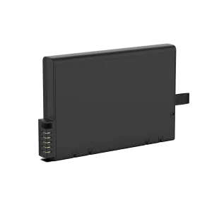
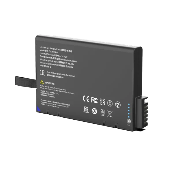
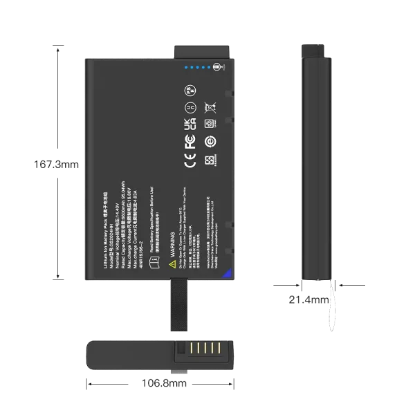
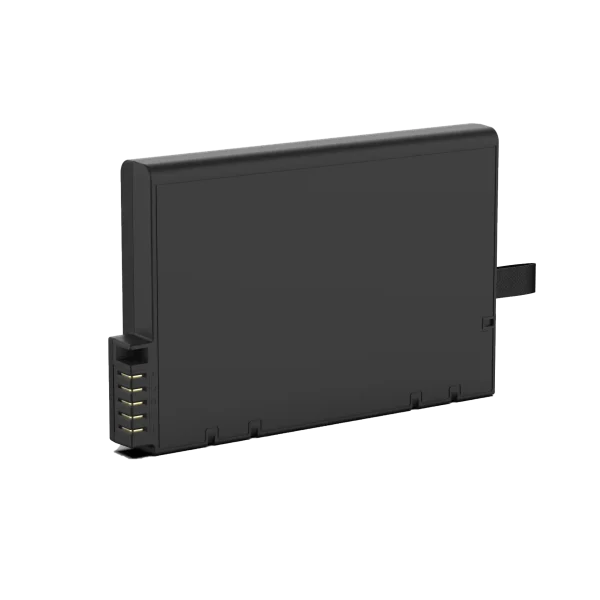
GS2024HH
14.4V/6900mAh/95.04Wh
Pack architecture and the SMBus smart battery
Once the energy target is set, the pack is configured as a series-parallel matrix: 1S for handheld transducer-class devices, 3S or 4S (11.1 V or 14.8 V nominal) for larger portables, with parallel strings added for capacity. Series configuration raises voltage and reduces current for a given power, which shrinks connector and trace losses; parallel strings add capacity and redundancy at pack level.
For medical devices we strongly prefer a smart battery with a System Management Bus (SMBus) interface. SMBus is a two-wire bus derived from I2C, and the Smart Battery Data Specification (v1.1)[8] from the Smart Battery System Implementers Forum defines the data flowing between the battery, the host and the charger: voltage, current, temperature, state of charge, remaining capacity, time-to-empty, cycle count and manufacturing data. The ultrasound mainboard simply reads these registers; the battery does the accounting.
A smart battery does not just report numbers, it computes them. A fuel gauge integrates coulomb counting with open-circuit voltage correction, then periodically recalibrates at full charge. With correct calibration, a well-designed gauge holds state-of-charge accuracy in the +-3 to 5 % range in normal use; without it, users see the phantom-percentage behaviour that generates field complaints. The same communication channel lets the host enforce safe charge current, show honest remaining time on the user interface, and log data for service diagnostics.
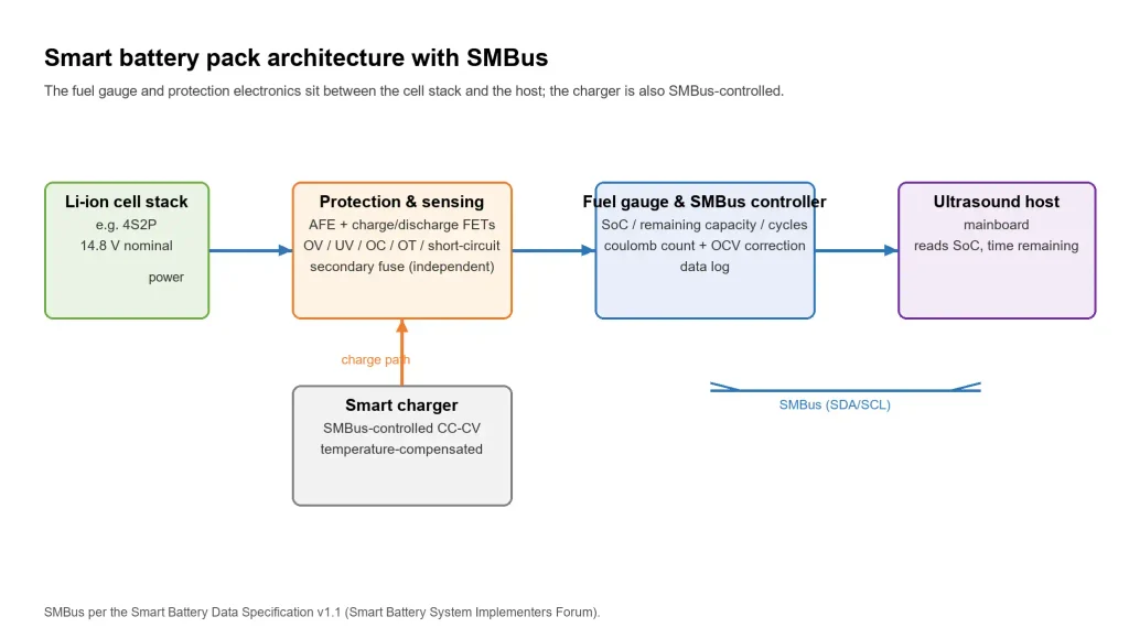
Figure 2 – Smart battery pack architecture with SMBus: the fuel gauge and protection electronics sit between the cell stack and the host; the charger is also SMBus-controlled.
BMS: protection and intelligence
The battery management system (BMS) is the layer that keeps lithium safe under both normal use and foreseeable misuse. A medical pack should implement, at minimum: over-voltage, under-voltage, over-current (charge and discharge), short-circuit, and over/under-temperature protection; independent hardware and firmware protection layers so that a software fault cannot disable the safety function; a secondary protection path such as a one-time fuse or eFuse that acts independently of the main protection IC; and charge/discharge FET control with pre-charge for deeply discharged cells.
Cell balancing matters the moment the pack is assembled in series. Passive balancing, dissipating excess energy from the highest cells as heat, typically at tens of milliamps, is sufficient for the small series counts and moderate charge currents of ultrasound packs, and it keeps the SoC estimate honest pack-wide. Finally, a medical-grade BMS records events: cycles, temperature extremes, protection trips and charge sessions. That log is gold for warranty analysis and for root-causing field returns.
Compliance: the certification map for a medical battery
A portable ultrasound battery sits in a regulatory intersection. Table 2 maps the standards that matter and what each one demands of the pack. As a rule, device-level standards are the responsibility of the finished device, while component-level standards are the responsibility of the battery supplier.
Table 2 – Standards governing a portable ultrasound battery pack
| Standard | Scope | What it means for the battery |
| IEC 62133-2:2017 | Safety of portable sealed lithium cells and batteries | Cell and pack pass tests for continuous low-rate charging, external short circuit, free fall, thermal abuse, crush, overcharge and forced discharge under intended use and foreseeable misuse. |
| UN 38.3 (Rev. 8 + Amd. 1) | Transport of lithium cells and batteries | Tests T1-T8 (altitude, thermal, vibration, shock, external short, impact/crush, overcharge, forced discharge) are required before the pack can be shipped by air, sea, road or rail. |
| IEC 62281 (2019 + Amd. 1 + Amd. 2) | Safety of lithium cells and batteries during transport | Complements UN 38.3 with additional transport-safety test requirements. |
| ISO 13485:2016 | Quality management for medical devices | The battery manufacturer runs a QMS for regulatory purposes: design control, risk management, traceability, change control. |
| IEC 60601-1 (Ed. 3.2) | General requirements for basic safety and essential performance of ME equipment | The battery is part of the ME equipment; it must not create hazards (overheating, fire, leakage) in normal and single-fault conditions. |
| IEC 60601-2-37:2024 | Particular requirements for ultrasonic diagnostic and monitoring equipment | The complete device, battery included, must comply with the ultrasound-specific safety and essential-performance requirements. |
| IEC 60601-1-2:2020 (Ed. 4.1) | EMC for ME equipment | The pack and its SMBus communication must not degrade immunity or emit beyond limits, relevant when a gauge talks on a bus next to a sensitive transducer front-end. |
A battery supplier’s obligations centre on the component level: cell and pack safety per IEC 62133-2:2017[1], transport per UN 38.3[5] and IEC 62281:2019+AMD1:2021+AMD2:2023[7], and a quality system per ISO 13485:2016[6]. The device manufacturer integrates the pack into an ME device that must satisfy the general requirements of IEC 60601-1:2005+AMD1:2012+AMD2:2020[2], the ultrasound-specific requirements of IEC 60601-2-37:2024 and the EMC requirements of IEC 60601-1-2:2020. Ask your battery supplier for the test reports and certificates up front, because they become part of your technical file.
Two practical warnings. First, IEC 60601-2-37:2024 is the current third edition[3]; older designs referenced the 2007 edition plus amendment 1:2015, so verify the edition in your target market’s regulatory framework. Second, EMC is a system property: a smart battery’s SMBus clock, and the switching of the charge path, can radiate into the transducer front-end. We co-validate EMC with the device team rather than treating the pack as a black box[4].
Thermal and mechanical design
Lithium cells are comfortable in a defined window. For NMC packs, charge is typically restricted to 0-45 C and discharge to about -10 to +50 C, with derating outside those ranges; confirm the exact numbers on the cell datasheet. The pack’s temperature sensors must be placed to capture both cell temperature and the thermal path to the enclosure, because a warm imaging device in a closed compartment heats the battery faster than a bench test suggests.
Mechanically, a medical pack must survive the device’s real life: repeated drops onto hard floors, vibration in transport, and connectors that get plugged and unplugged thousands of times. The battery enclosure, cell retention, connector keying (so that a wrong connector physically cannot mate) and strain relief are all part of the design. If the pack is field-replaceable, the mechanical interface must also survive repeated insertions without compromising the ingress-protection rating or creating pinch hazards.
Charging strategy and battery care
Charging is where many batteries are killed early. The standard profile is constant current then constant voltage (CC-CV): typically 0.5 C to the cell’s charge limit, then constant voltage with a termination current at a few percent of rated capacity. Charge current and termination must be temperature-compensated, and charging must be inhibited below 0 C, because lithium plating at cold temperature is a safety and life concern, not a convenience.
Storage matters too. A pack stored at 100 % SoC ages faster and carries more stored energy in the warehouse; we recommend storage at roughly 30-60 % SoC for distribution and a similar range for long idle periods. With moderate depth of discharge and sensible thermal management, an NMC pack in this application should comfortably deliver several hundred cycles, enough for years of clinical service when the device is properly maintained. Set the cycle-life expectation with your supplier up front and put it in the specification, because it becomes a warranty line item.
Validation: what we test before release
In our laboratory, validation starts with the cell: cycle-life testing at 25 C and at elevated temperature, DC-resistance growth, and capacity retention to the supplier’s claimed end of life. At pack level we run the abuse and environmental tests required by IEC 62133-2:2017[1], including external short circuit, overcharge, thermal abuse, crush and free fall, and the full T1-T8 sequence of UN 38.3 for transport[5].
On top of the mandatory tests, we run application-level validation: a representative clinical duty cycle scripted in the lab, charge and discharge at temperature extremes, SMBus data-accuracy audits against a reference meter, EMC pre-compliance with the device team, and a field pilot with clinicians who log real usage. The goal is not just a certificate, it is knowing how the pack behaves on the hundredth day in a busy clinic.
A practical spec checklist for OEMs
When you write your battery requirement, here is the checklist we hand to every OEM customer (Table 3).
Table 3 – What to specify when sourcing a portable ultrasound battery
| Item | What to specify |
| Clinical runtime | Hours per day without a mains socket, worst realistic duty cycle |
| Nominal voltage & capacity | e.g. 14.8 V, 6.8 Ah (about 100 Wh), driven by the power budget |
| Charge time & input | Charge current, ambient temperature range, connector and input spec |
| Interface | SMBus / Smart Battery Data v1.1, register map, polling rate |
| BMS & protections | Full protection set, dual-layer safety, secondary fuse, balancing |
| Environment | Operating and storage temperature, humidity, ingress rating, drop class |
| Certifications & reports | IEC 62133-2, UN 38.3, IEC 62281, ISO 13485 documentation |
| Lifecycle | Cycles to 80 % capacity, warranty terms, spare and replacement plan |
| Documentation | Test reports, datasheet, DFMEA summary, transport test summary |
| Supplier capability | Medical battery track record, design-for-manufacture, traceability |
Closing: engineering principle
The battery is not an accessory; it is a medical component with its own safety, quality and communication responsibilities. Start from the clinical use pattern, translate it into a power budget, let the budget choose the chemistry and the pack size, and hold the pack, and your supplier, to the standards the finished device must meet. When the battery is boringly reliable, nobody notices it. That is precisely the goal.
About the author: the author is a Senior R&D Engineer in battery systems at TEFOO (Shenzhen, China), an OEM battery designer and manufacturer serving medical equipment makers, with hands-on experience in cell selection, BMS design, SMBus smart-battery integration and medical compliance. TEFOO builds custom packs for portable medical devices under ISO 13485-aligned quality processes.
Disclaimer: this article reflects engineering practice and is for general information only. Illustrative figures are design examples, not guarantees; validate against measured data, cell datasheets and the regulatory framework for your target market. It is not medical advice and does not replace regulatory assessment for a specific device.
References
- IEC 62133-2:2017, Secondary cells and batteries containing alkaline or other non-acid electrolytes – Safety requirements for portable sealed secondary cells, and for batteries made from them, for use in portable applications – Part 2: Lithium systems. IEC Webstore. https://webstore.iec.ch/en/publication/32662
- IEC 60601-1:2005+AMD1:2012+AMD2:2020 (Edition 3.2), Medical electrical equipment – Part 1: General requirements for basic safety and essential performance. IEC Webstore. https://webstore.iec.ch/preview/info_iec60601-1%7Bed3.2%7Den.pdf
- IEC 60601-2-37:2024 (Edition 3.0), Medical electrical equipment – Part 2-37: Particular requirements for the basic safety and essential performance of ultrasonic medical diagnostic and monitoring equipment. VDE Verlag preview. https://www.vde-verlag.de/iec-normen/preview-pdf/info_iec60601-2-37%7Bed3.0.RLV%7Den.pdf
- IEC 60601-1-2:2020 (Edition 4.1), Medical electrical equipment – Part 1-2: General requirements for basic safety and essential performance – Collateral standard: Electromagnetic disturbances – Requirements and tests (recognized consensus standard, US FDA). https://www.accessdata.fda.gov/scrIpts/cdrh/cfdocs/cfStandards/results.cfm?ascapilotyn=off&sortcolumn=st&start_search=701
- UN Manual of Tests and Criteria, Section 38.3 (UN 38.3), eighth revised edition (2023) with Amendment 1 (2025), United Nations Economic Commission for Europe. https://unece.org/sites/default/files/2025-06/ST-SG-AC10-C3-2025-21E.pdf
- ISO 13485:2016, Medical devices – Quality management systems – Requirements for regulatory purposes. International Organization for Standardization. https://www.iso.org/obp/ui/es/#!iso:std:59752:en
- IEC 62281:2019+AMD1:2021+AMD2:2023, Safety of primary and secondary lithium cells and batteries during transport. IEC Webstore. https://webstore.iec.ch/publication/83426
- Smart Battery System Implementers Forum (SBS-IF), Smart Battery Data Specification, Revision 1.1. https://sbs-forum.org/specs/sbdata10.pdf
- A&S Power, Portable Ultrasound Machine Battery Design: Engineering Guide for OEM Manufacturers (2026). https://www.szaspower.com/industry-news/portable-ultrasound-machine-battery-design.html
- KONTED, C10MR Pocket Ultrasound System – Technical Data Sheet. https://www.kontedmed.com/uploads/file/c10mr-technical-data-sheets.pdf
- Universal Diagnostic Solutions, TE Air Wireless Handheld Ultrasound System – Performance Specifications (North America). https://www.ultrasoundportables.com/images/brochures/TE_Air_e5M_Ultrasound_Datasheet_North_America.pdf