An OEM engineering guide to voltage, cell configuration, BMS protection, and supplier qualification
The engineering answer
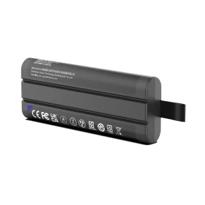
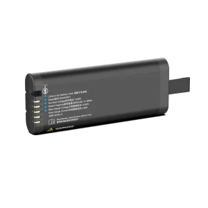
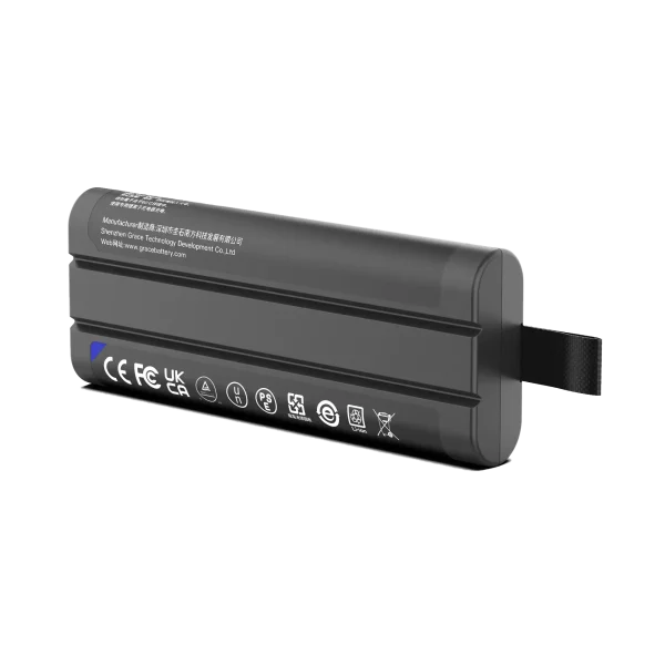
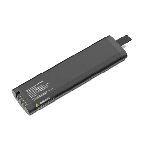
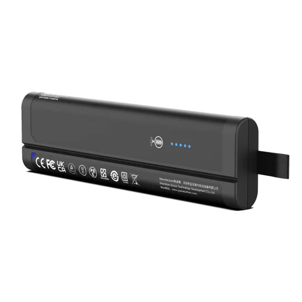
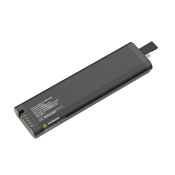
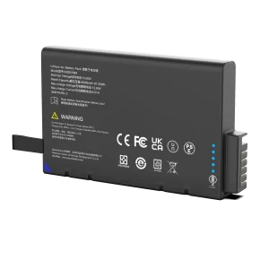
A 10.8V 3S lithium-ion battery pack is a three-cell-series architecture whose nominal voltage depends on the selected cell specification. It can be a good fit for equipment designed around that pack’s complete operating-voltage range, current profile, charge method, and mechanical envelope. The label does not tell a buyer the usable capacity, runtime, peak-current capability, safety evidence, or suitability for a particular device.
When evaluating a 10.8V 3S lithium ion battery pack supplier, start with the device requirements and ask for evidence against them. A capable customized lithium battery manufacturer should explain its cell choice, protection design, assembly controls, verification plan, and configuration-specific compliance documents. Those details determine whether a sample can move safely toward production.
What 10.8V and 3S mean
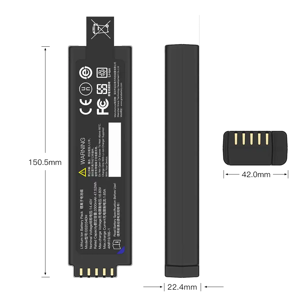
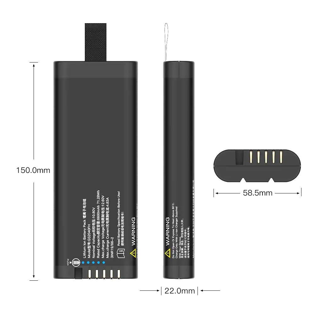
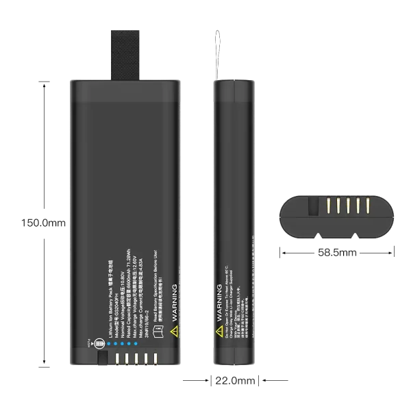
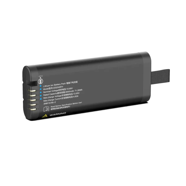
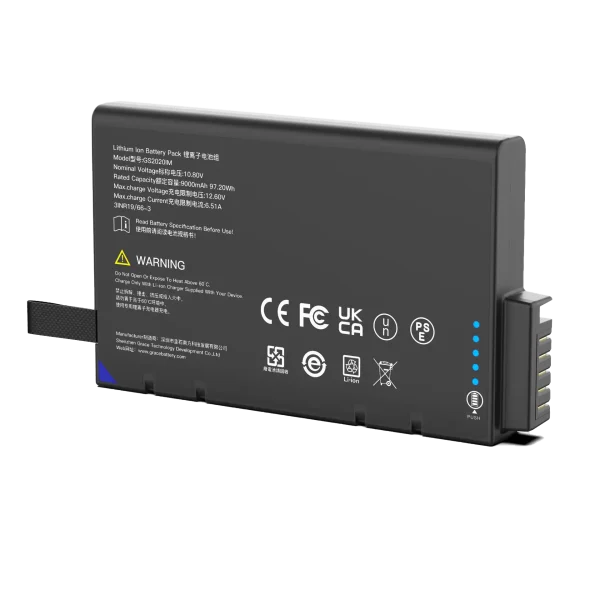
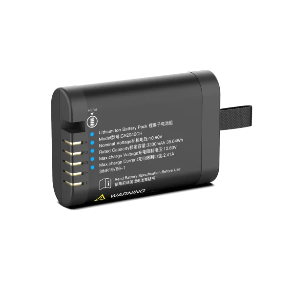
The term 3S means three cells or cell groups connected in series. In a common lithium-ion design using cells rated around 3.6V nominal, three in series give 10.8V nominal. Some cell datasheets use a different nominal voltage, so the pack rating must be tied to the exact cell chemistry and datasheet. Pack voltage changes with state of charge, load, and temperature.
A 3S pack’s charge limit is not 10.8V. For cells whose specified charge limit is 4.2V per cell, the corresponding pack charge limit is 12.6V. Other lithium-ion chemistries may specify different limits. The charger, BMS thresholds, cell specification, and device input range must all agree; a charger should never be selected from the nominal-voltage label alone.
The parallel count is a separate choice. A 3S1P pack has three cells; a 3S2P pack has six, arranged as three series groups with two matched cells in parallel in each group. Series connection raises voltage. Parallel connection increases amp-hour capacity and can share load current, subject to cell matching, interconnect resistance, thermal design, and protection. Watt-hours are estimated from nominal voltage multiplied by amp-hours, but usable energy depends on the discharge limits and operating conditions.
| Pack label | Typical layout | What it tells you |
| 3S1P | 3 cells, one in each series group | Series count and parallel count; not the capacity or current rating. |
| 3S2P | 6 cells, two parallel cells in each of three series groups | Higher capacity may be possible; verify current sharing and actual cell data. |
| 10.8V nominal | Three cells rated near 3.6V nominal each | Nominal reference only; confirm the selected cell’s full voltage limits. |
Translate the device into a battery specification
Before requesting a quotation, measure the load at the battery terminals. Record standby current, normal operating current, startup and transmit peaks, pulse duration, event frequency, and shutdown behavior. A device with motors, radios, heaters, pumps, or high-brightness displays may draw short peaks that a capacity-only calculation misses. Capture the minimum input voltage during those peaks because voltage sag can reset a device while the pack still contains energy.
Estimate energy from the actual duty cycle. For a first-pass calculation, multiply current by time for each operating state and sum the results. Then account for conversion losses, the permitted depth of discharge, the temperature range, aging, and the desired service interval. Treat calculated runtime as an estimate until a production-representative pack has been tested in the real device.
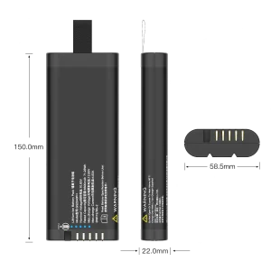
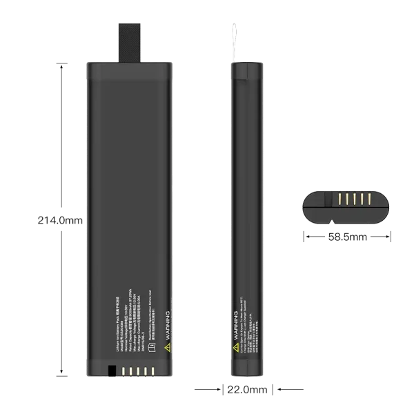
Specify minimum and maximum pack voltage, continuous and peak current, pulse duration and repetition, target runtime, charging profile, operating and storage temperatures, dimensions, connector and pinout, enclosure constraints, annual volume, and target markets. If the device must keep running during a peak load or brownout, state that acceptance limit as a measurable voltage and duration.
Cell selection and pack construction
Cell selection is a trade-off among energy density, discharge capability, cycle life, temperature limits, availability, and qualification records. Use the cell manufacturer’s controlled datasheet and application guidance to confirm charging, discharge, storage, and thermal limits. Do not substitute an apparently similar cell without reviewing its effect on capacity, impedance, protection settings, charger compatibility, pack dimensions, and compliance evidence.
For parallel groups, use cells with an approved common specification and production controls. Differences in state of charge, impedance, age, or interconnect resistance can create unequal current sharing. The pack design should define cell sourcing, matching or screening criteria, weld process, insulation, temperature-sensor location, wire routing, and end-of-line checks. These controls are part of the electrical design because resistance and heat in the assembly affect usable power.
BMS protection and charger compatibility
A multi-cell pack usually needs a battery management system or equivalent protection architecture suited to the selected cells and product. The design may monitor individual series-group voltages and temperature and provide responses to overcharge, over-discharge, overcurrent, or short-circuit conditions. The thresholds, delays, recovery behavior, and current ratings must follow the cell limits and the device’s fault analysis. A BMS label alone does not establish how the pack behaves under a specific fault.
Ask how the pack protects against faults and what happens after a protection event. Confirm whether it includes cell balancing, how balancing is implemented, quiescent current, temperature sensing, fault latching or recovery, and any communication interface. If the pack includes a fuel gauge or SMBus interface, define the supported commands, data accuracy conditions, connector pins, firmware revision, and host behavior when data is missing or implausible. Host software should not replace independent pack protection.
The charger must match the selected chemistry, series count, charge voltage, current, termination method, and temperature limits. Review charging in the finished device, including the power path and any load sharing between the charger and system. Do not assume that two products described as lithium-ion can share a charger or BMS configuration.
Mechanical and thermal integration
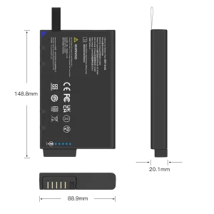
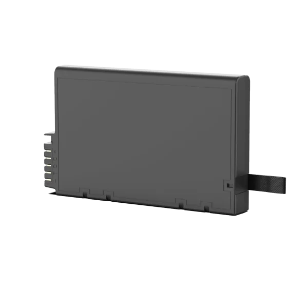
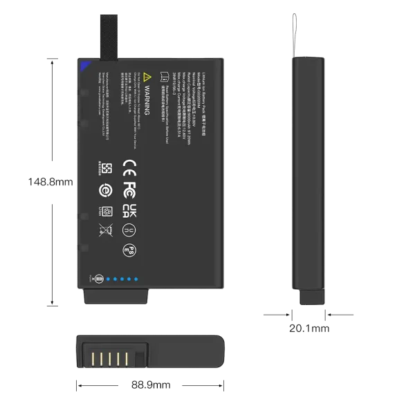
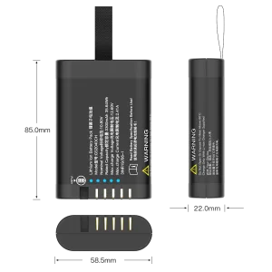
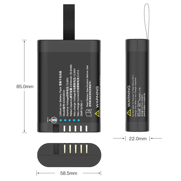
The pack must fit without loading cells, tabs, welds, or the connector in ways the assembly cannot tolerate. Review cell restraint, clearance, insulation, strain relief, connector retention, cable bend radius, enclosure ventilation, and service access. Temperature sensors need a defined location that represents cell temperature under expected charge and discharge conditions. Validate heating and voltage drop in the actual enclosure, not only on an open bench.
For replaceable packs, assess keying, polarity protection, contact sequencing, and the chance of incorrect replacement. For sealed equipment, consider service life, field replacement, end-of-life handling, and how the pack can be removed without damaging the product. These choices affect reliability and maintenance cost, so include them in the initial supplier brief.
Safety, transport, and market evidence
Different standards address different questions. IEC 62133-2 covers safety requirements and tests for portable sealed secondary lithium cells and batteries within its scope. UN Manual of Tests and Criteria subsection 38.3 concerns transport testing for lithium cells and batteries. Transport test evidence does not by itself demonstrate product safety or conformity of the finished equipment.
For medical electrical equipment, IEC 60601-1 addresses equipment-level basic safety and essential performance. A battery pack report alone does not show that the finished device meets those requirements. The device manufacturer must assess the pack together with the charger, power path, enclosure, alarms, intended use, and foreseeable fault conditions under the applicable conformity process. Exact requirements depend on market, product category, edition, and certification route; confirm applicability with the responsible compliance specialist or laboratory.
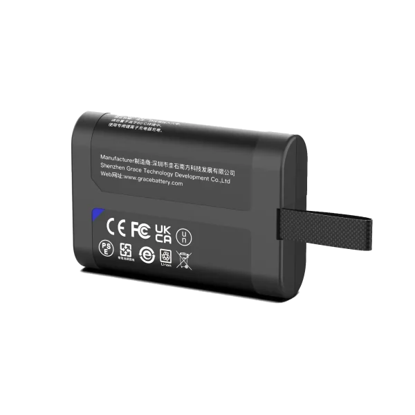
Ask the supplier to identify the exact pack model and configuration covered by each report. Relevant records may include cell documentation, controlled drawings and bill of materials, protection thresholds, transport test summary, test laboratory and report scope, production traceability, change-control procedure, and end-of-line acceptance tests. A report for a similar pack is not automatically evidence for a changed cell, circuit, enclosure, or series/parallel configuration.
How to qualify a supplier
A supplier review should test both engineering capability and production control. Ask the team to explain the design decisions in language that your electrical, mechanical, sourcing, and compliance teams can review. Request sample test data with the pack configuration, cell model, firmware revision, load, temperature, and method stated. Then compare the evidence with the product specification and acceptance criteria.
| Ask the supplier | Evidence to review |
| Which cells and configuration are quoted? | Controlled cell datasheet, pack drawing, bill of materials, and approved alternatives. |
| What voltage and current limits apply? | Charge and discharge limits, peak pulse conditions, protection thresholds, and test records. |
| How is each pack checked in production? | End-of-line electrical test, traceability, sampling plan, and nonconformance process. |
| What changes require customer approval? | Written change-control scope for cells, components, firmware, materials, and manufacturing site. |
| What market evidence is available? | Configuration-specific reports and an explanation of their scope and limitations. |
Validation before production release
Verify the pack in the finished device using production-representative hardware and firmware. Measure capacity or energy under the agreed method, voltage sag during worst-case pulses, charging behavior, temperature rise, and cutoff or recovery behavior. Exercise normal operation and relevant faults such as a stalled load, interrupted connection, temperature-sensor fault, communication loss, or incorrect charger where those scenarios apply to the risk assessment.
Set acceptance limits before testing. Define the sample configuration, test equipment, temperatures, state of charge, firmware, sample count, and pass/fail criteria. Repeat critical checks after a design change or supplier change when the change can affect safety, performance, mechanical fit, or compliance. This produces evidence for the product configuration that will actually ship.
Frequently asked questions
Is a 10.8V 3S pack fully charged at 10.8V?
No. 10.8V is a nominal rating for a common three-series-cell pack using cells rated near 3.6V nominal. The charge limit comes from the selected cell datasheet. For a 4.2V-per-cell charge limit, the three-cell limit is 12.6V; other chemistries can differ.
Does 3S tell me the battery capacity?
No. 3S describes the series count. Capacity depends on the selected cells and parallel count, while usable energy depends on the load, cutoff limits, temperature, aging, and power-conversion losses.
Can I use any 12.6V charger with a 3S pack?
No. The charger must also match the cell chemistry, charge current, termination method, temperature rules, and pack protection design. Confirm compatibility against the specific cell and pack specifications.
What does a customized lithium battery manufacturer need for a quotation?
Provide the voltage range, continuous and peak load profile, runtime target, charging method, dimensions, connector, operating conditions, target markets, forecast volume, and required tests or documentation.
Does UN 38.3 certify a battery pack for use in a device?
UN 38.3 addresses transport testing. It does not replace product safety evaluation or establish conformity of the finished device.
Conclusion
Select the pack against the finished device’s voltage range, usable energy, peak load, charger, protection needs, and mechanical limits. Require configuration-specific test data and production controls before release.
References
– IEC 62133-2, Safety requirements for portable sealed secondary lithium cells and batteries. https://webstore.iec.ch/en/publication/32662
– IEC 60601-1, Medical electrical equipment – General requirements for basic safety and essential performance. https://webstore.iec.ch/en/publication/67497
– United Nations Economic Commission for Europe, Manual of Tests and Criteria resources. https://unece.org/transport/dangerous-goods/rev8-files
– Smart Battery System specifications. https://smbus.org/specs/