An engineering guide to 4-series pack design, supplier evaluation, and product validation
The short answer
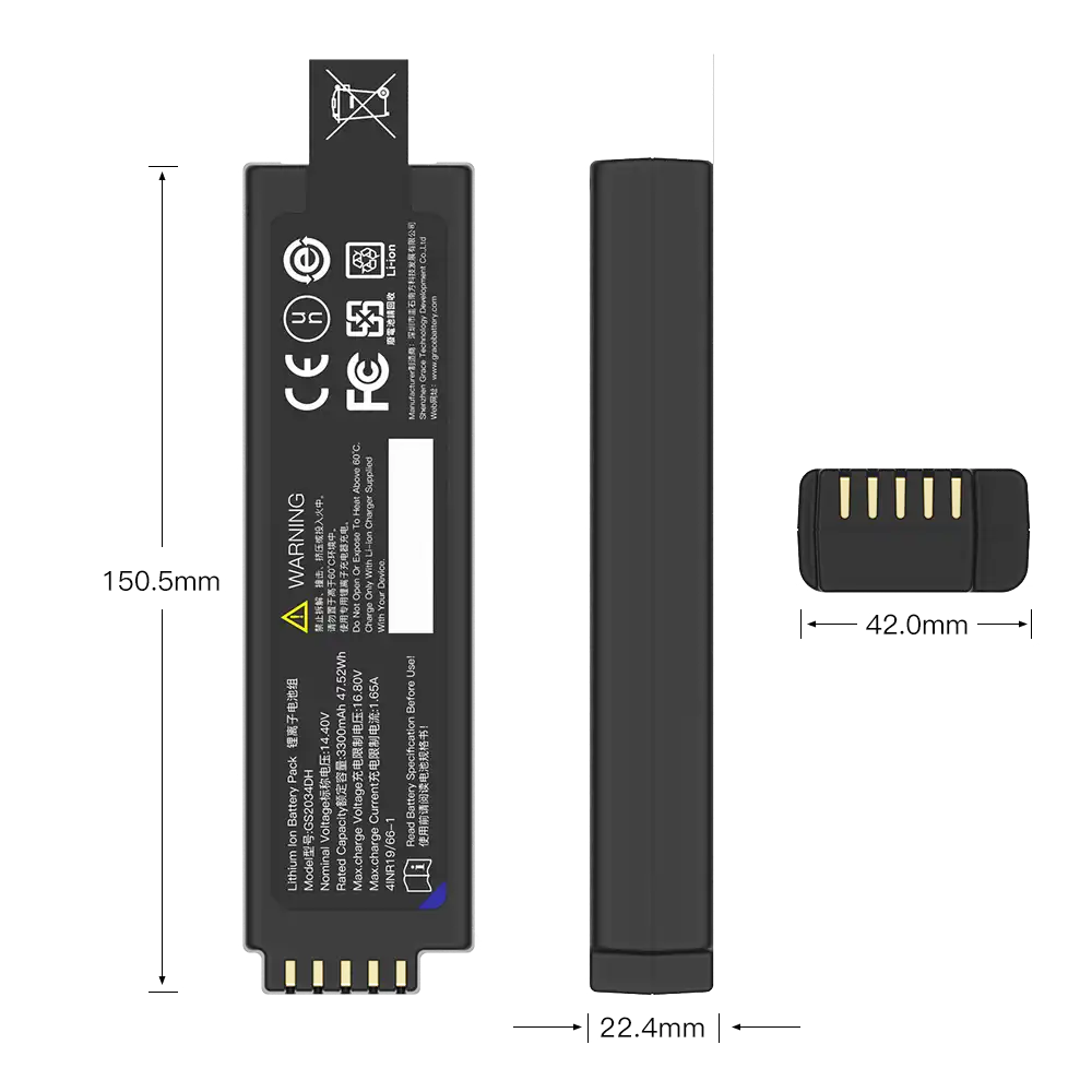
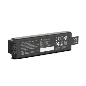
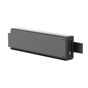
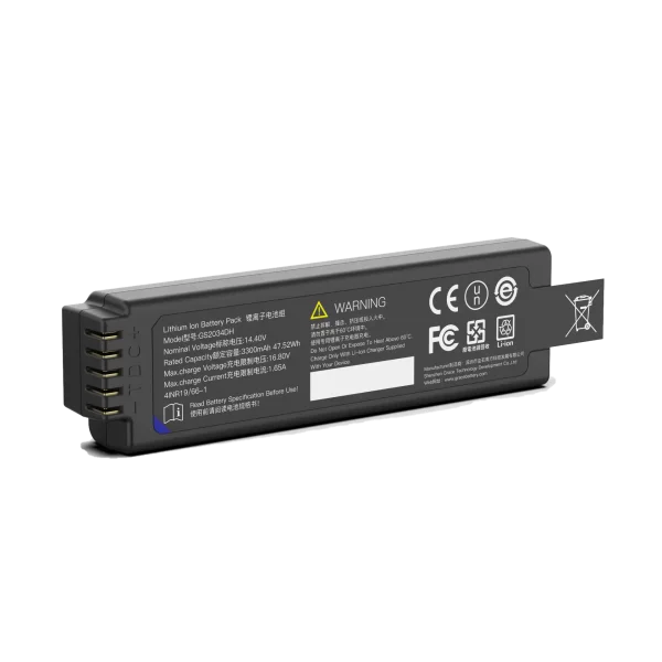
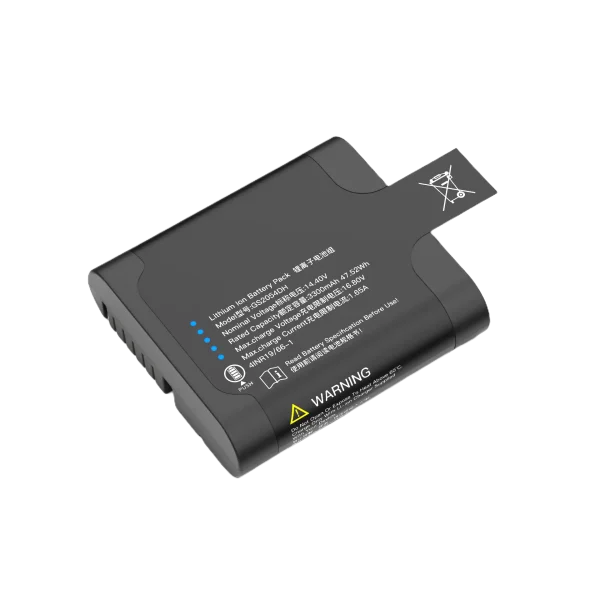
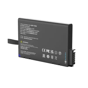
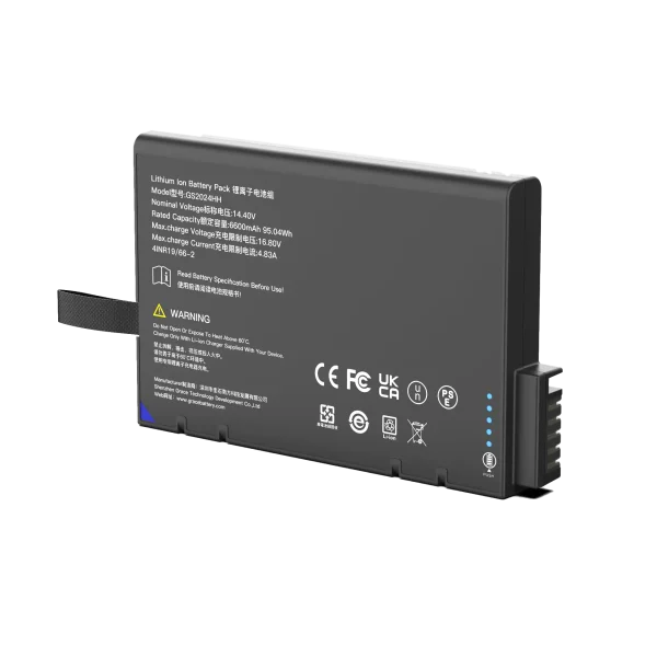
A 14.4V 4S lithium-ion battery pack is a four-cell-group series design intended for equipment whose power system can accept the pack’s full operating-voltage range. The 14.4V label describes a nominal voltage convention; it does not specify capacity, runtime, current capability, charging limits, connector, protection behavior, or compliance status. Those parameters must be engineered around the device.
When selecting a 14.4v 4s lithium ion battery pack supplier, start with the electrical and mechanical requirements and ask for evidence tied to the exact proposed configuration. A qualified customized lithium battery manufacturer should be able to explain cell selection, battery management, charging compatibility, validation, traceability, and design-change control in terms your product team can verify. This guide is for OEM engineers and purchasing teams preparing that evaluation.
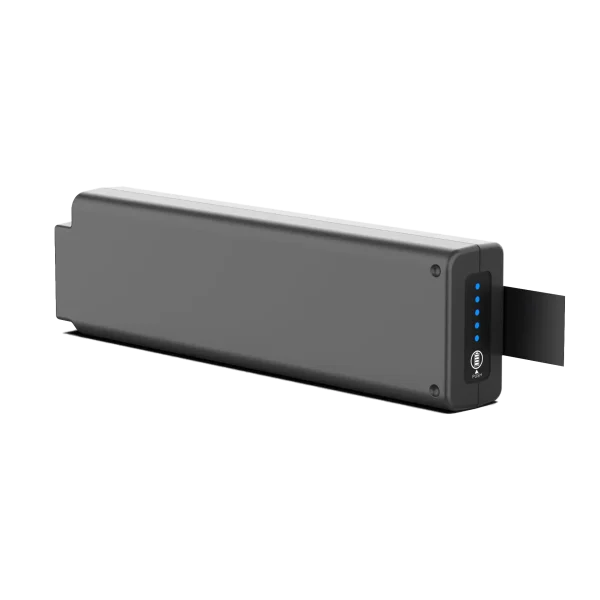
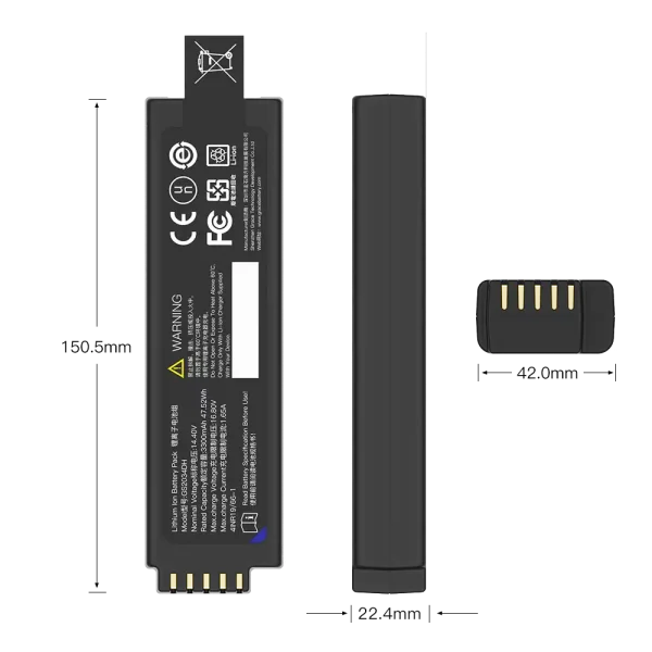
What 14.4V and 4S mean
In a common lithium-ion design using cells with a nominal voltage around 3.6V, four groups in series produce a nominal pack voltage around 14.4V. Series connection raises voltage; it does not add amp-hour capacity. The actual pack voltage varies with state of charge, load, temperature, cell chemistry, and the cell manufacturer’s operating limits. Some product listings use 14.4V and 14.8V conventions for four-series lithium-ion packs. Do not infer charge voltage from the marketing label: use the selected cell datasheet and approved charging specification.
The configuration is written 4SxP. Four series groups define the voltage; the number of parallel cells in each group determines capacity and current capability, subject to cell limits and the pack design. For example, 4S1P uses four cells, while 4S2P typically uses eight. In an ideal matched arrangement, adding parallel capacity increases amp-hours, but usable energy and discharge performance depend on cell characteristics, interconnect resistance, BMS limits, temperature, aging, and load profile.
A device designed only around nominal voltage can reset or operate unpredictably near the top or bottom of the battery’s permitted range. Provide the system designer with the specified minimum and maximum pack voltage, current limits, dynamic load behavior, and low-voltage shutdown strategy. Verify that DC/DC converters, motors, relays, indicators, and charging electronics tolerate those conditions.
Start with the device load and runtime
A useful battery requirement begins with a measured load profile. Record standby consumption, typical operating current, startup surges, radio transmission, motor stalls, heater or pump duty, and simultaneous charging if the device supports it. For a first-order energy estimate, multiply average power by required operating time, then add engineering margin for conversion losses, temperature, aging, cutoff reserve, and production variation. This estimate narrows the design space; it is not a substitute for validation on the real device.
Peak current can matter more than average energy. A short pulse may trigger overcurrent protection or pull the voltage below the device’s reset threshold even when the pack has ample remaining capacity. Ask the supplier to state continuous and pulse discharge limits, pulse duration and repetition assumptions, voltage sag conditions, and relevant thermal limits. Match those claims to the actual load waveform and test setup.
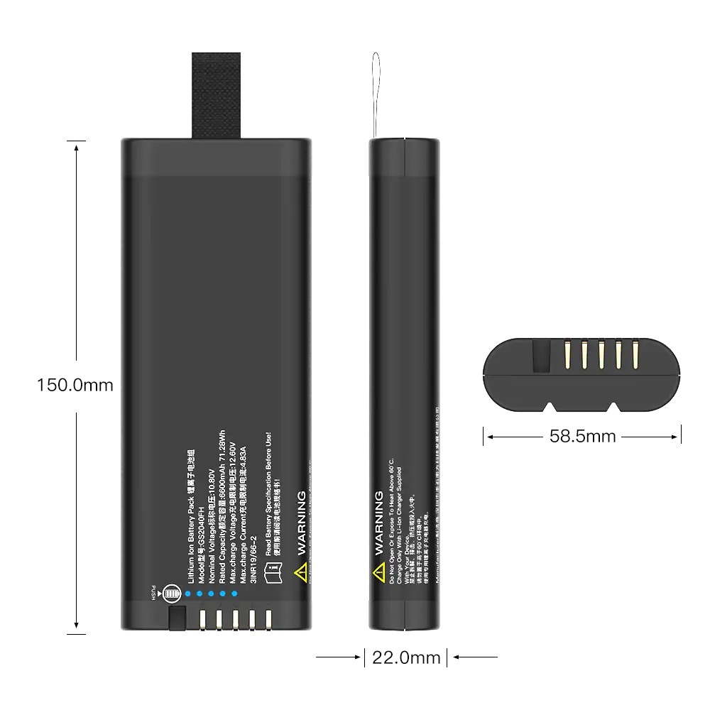
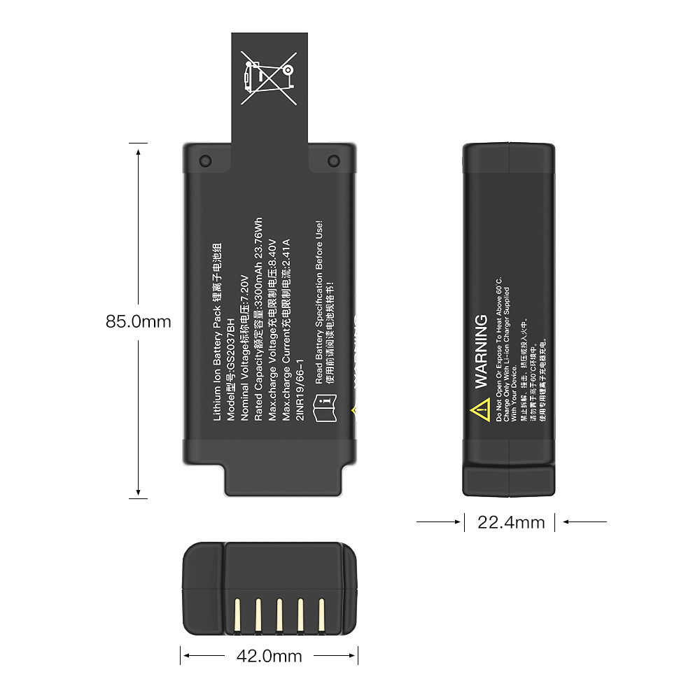
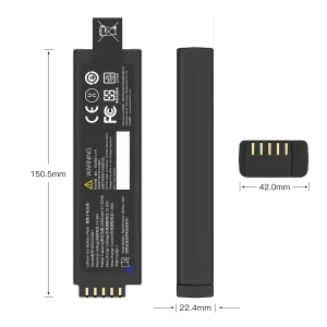
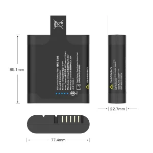
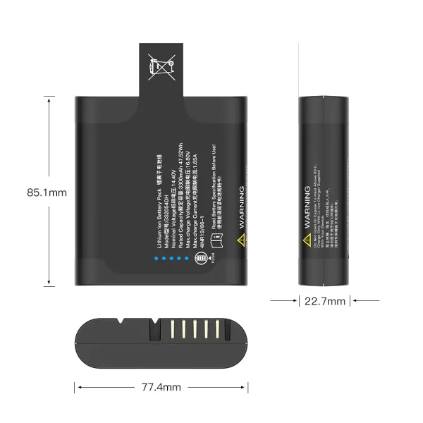
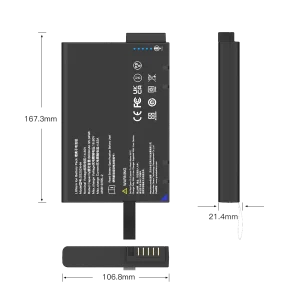
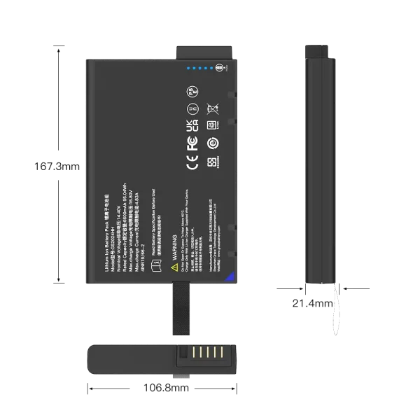
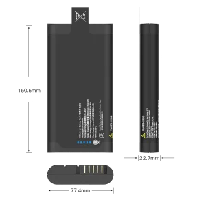
Translate the enclosure into constraints as well: maximum dimensions and mass, mounting orientation, connector and cable exit, retention features, operating and charging temperatures, vibration exposure, ingress protection, and service access. Early drawings and interface-control documents reduce late changes to tooling, cabling, and host firmware.
How to specify a customized 4S pack
Cell selection should balance energy density, discharge rate, cycle life, temperature range, availability, and documented qualification. The manufacturer should identify the cell model and chemistry in the controlled design record, explain why it fits the use case, and define how approved alternates are evaluated. Cells used in a pack need controlled sourcing and matching; assembly quality, insulation, weld integrity, and interconnect resistance also affect performance and safety.
The battery management system (BMS) typically monitors cell-group voltage and temperature and controls charge and discharge through protection switches. Define the required responses to overcharge, over-discharge, overcurrent, short circuit, and temperature extremes. Thresholds, delays, recovery behavior, sensor placement, and host-side alarms should be coordinated with the cell specification and product risk analysis. A BMS feature list alone does not demonstrate correct protection; request the design limits and test evidence.
Specify whether the pack is two-wire or includes data communication, what the host needs to read, and how low-battery and fault states are handled. If a fuel gauge or SMBus interface is needed, agree on the command set, electrical levels, connector pinout, data accuracy conditions, startup behavior, and firmware identification. Define what the host should do when data is stale, implausible, or unavailable. Critical electrical protection should not depend solely on application software.
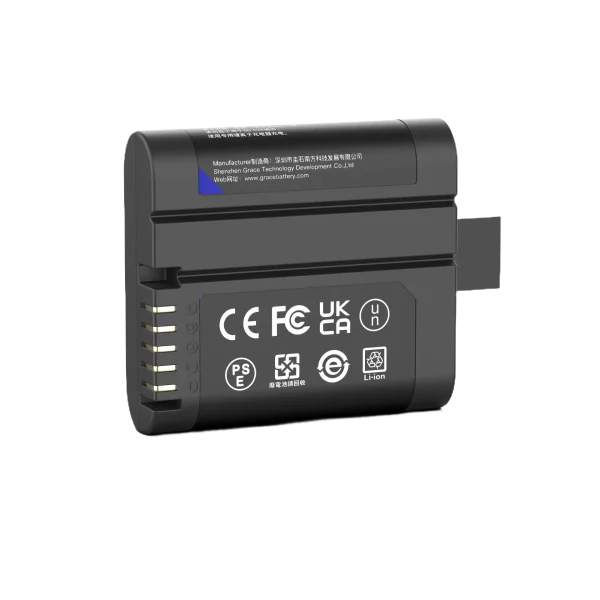
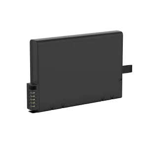
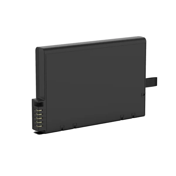
Mechanical details deserve the same discipline as electrical ones. Review drawings for cell restraint, clearances, insulation barriers, strain relief, connector keying, wire routing, temperature-sensor contact, and thermal paths. Confirm that the pack can be assembled consistently and serviced as intended. Specify label content, lot identification, packaging, and end-of-life handling for the target sales regions.
Charging and system compatibility
A 4S lithium-ion pack must be paired with a charger profile approved for the exact cells and pack limits. Confirm charge voltage, current, termination method, temperature conditions, charge inhibit behavior, and any required cell balancing strategy from the design documentation. A charger for a different series count or chemistry is not interchangeable because its connector fits. If the battery charges inside the product, test the complete power path, including simultaneous system load, thermal behavior, and fault response.
Establish which component owns each function: the charger regulates charging, pack circuitry enforces battery-level limits, and host firmware manages product behavior and user indications. Document interactions during insertion, removal, brownout, interrupted charging, sensor faults, and communication loss. Test these interactions with production-representative hardware rather than relying only on component-level simulations.
Safety, transport, and compliance evidence
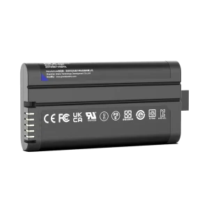
Applicable requirements depend on battery construction, end product, destination markets, and intended use. IEC 62133-2 addresses safety requirements for portable sealed secondary lithium cells and batteries. UN Manual of Tests and Criteria subsection 38.3 concerns transport testing for lithium batteries. They address different purposes; documentation for one does not substitute for the other. Check current editions, national adoptions, and shipment rules with the responsible compliance specialist or qualified laboratory.
For regulated equipment, evaluate the battery in the context of the finished system and its risk-management process. A battery report alone does not establish that the complete product is compliant. Keep the exact pack model, cell model, BMS revision, firmware, critical components, test configuration, and report scope traceable. Supplier claims should identify the tested configuration and issuing laboratory so the product team can confirm relevance.
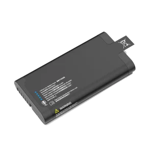
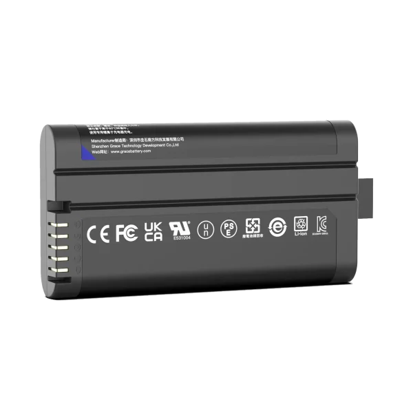
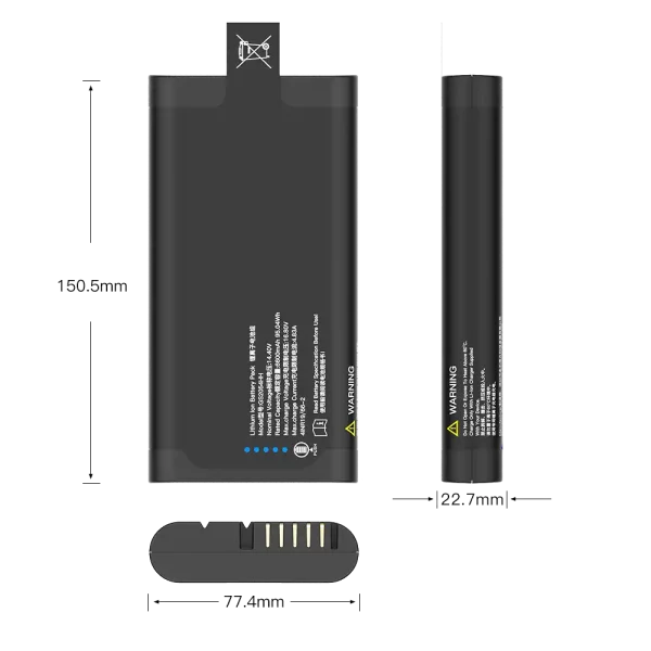
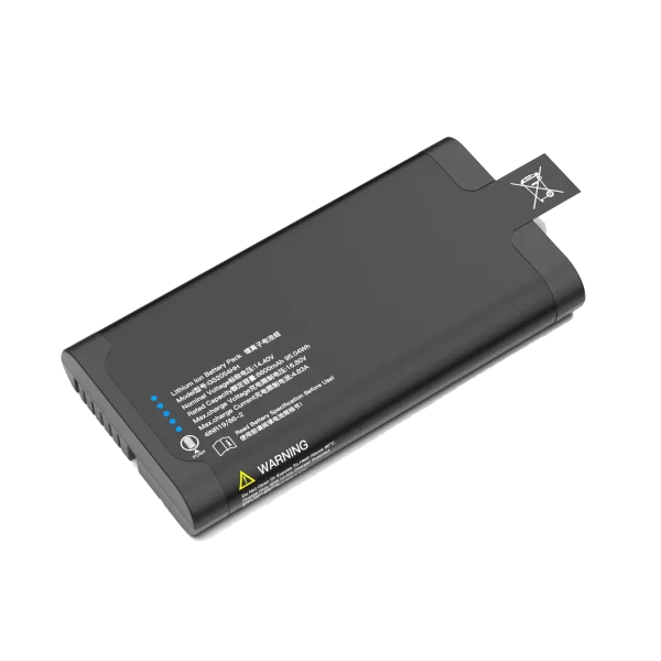
How to evaluate a 14.4V 4S battery pack supplier
Ask prospective suppliers to show how they move from requirements to a controlled design: requirement review, cell selection rationale, electrical and mechanical drawings, BMS architecture, prototype builds, verification plan, and production release. Request sample-to-production traceability, incoming cell controls, assembly inspection criteria, end-of-line tests, nonconformance handling, and notification rules for changes to cells, materials, firmware, manufacturing site, or process.
Review technical evidence rather than relying on generic capability statements. Useful evidence includes a complete specification, test conditions and acceptance criteria, capacity and runtime results, protection tests, charge behavior, temperature data, communication validation where applicable, and transport documentation for the exact configuration. Ask how anomalies are investigated and how corrective actions are verified. A responsive engineering contact and clear revision control reduce ambiguity throughout product life.
A request for quotation should include the device voltage window, current waveform, runtime target, charging architecture, operating and storage temperatures, enclosure drawing, connector, communications needs, target markets, expected volume, lifecycle expectations, and required documentation. State which requirements are fixed and which can be optimized. Compare proposals against the same assumptions so price and lead time do not hide differences in cell, capacity rating conditions, BMS behavior, or validation scope.
Validation before release
A release plan should verify the pack as both a battery and a subsystem of the product. Depending on intended use, testing may include capacity and runtime at defined loads and temperatures, charge termination, voltage sag, protection thresholds, recovery behavior, sensor accuracy, communication fault handling, connector retention, vibration or shock, and thermal performance in the actual enclosure. Set acceptance limits before testing and use production-representative samples.
Exercise normal operation and foreseeable faults, such as a stalled motor, blocked airflow, interrupted connection, incorrect host request, or loss of battery data. Confirm the device responds predictably and displays the intended warning before shutdown when the design requires it. Retain test configuration, instrument calibration, sample identifiers, firmware versions, results, and deviations in the product record.
Frequently asked questions
Is a 14.4V 4S pack the same as a 14.8V pack? Not necessarily as a specification. Both labels can refer to four-series lithium-ion conventions, but cell chemistry, nominal-voltage convention, maximum charge voltage, and operating limits must be checked in the actual datasheet and pack specification.
How do I estimate runtime? Use measured device energy consumption over the full use cycle and compare it with the pack’s usable energy under the intended load, temperature, cutoff, and aging conditions. Rated capacity alone does not predict runtime in every application.
Can I use any 4S lithium-ion charger? No. Charger voltage, current, termination, temperature handling, and compatibility must match the selected cells and pack design. Confirm the approved charging interface with the battery and device engineers.
What should I send a customized lithium battery manufacturer? Provide voltage limits, load profile and peaks, runtime, charging method, dimensions, connector, environmental conditions, communications, target markets, volume, and required evidence. A drawing and measured load data improve the accuracy of the proposal.
Conclusion
The right 14.4V 4S pack is the one whose documented limits, cell configuration, protection behavior, charging interface, mechanical design, and evidence fit the finished product. Evaluate a 14.4v 4s lithium ion battery pack supplier on the quality of that engineering process and the traceability of its claims. A customized lithium battery manufacturer should make assumptions explicit, validate the agreed requirements, and control changes through production and product life.
Technical references
– IEC 62133-2, Safety requirements for portable sealed secondary lithium cells and batteries. https://webstore.iec.ch/en/publication/32662
– UNECE, Manual of Tests and Criteria, subsection 38.3 and lithium battery transport guidance. https://unece.org/transport/dangerous-goods/rev8-files
– IEC, IEC 62619: Secondary lithium cells and batteries for industrial applications. https://webstore.iec.ch/en/publication/64073
Engineering note: Voltage conventions and applicable requirements vary by cell, pack design, product, and market. Confirm values and standards for the selected configuration before release.