Technical Engineering Blog | Prepared by a senior lithium-ion R&D engineer | Application note for system integrators and LiDAR OEMs
Executive Summary
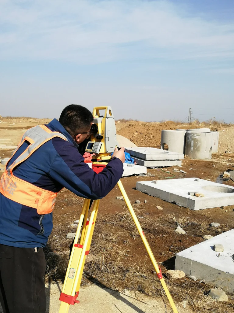
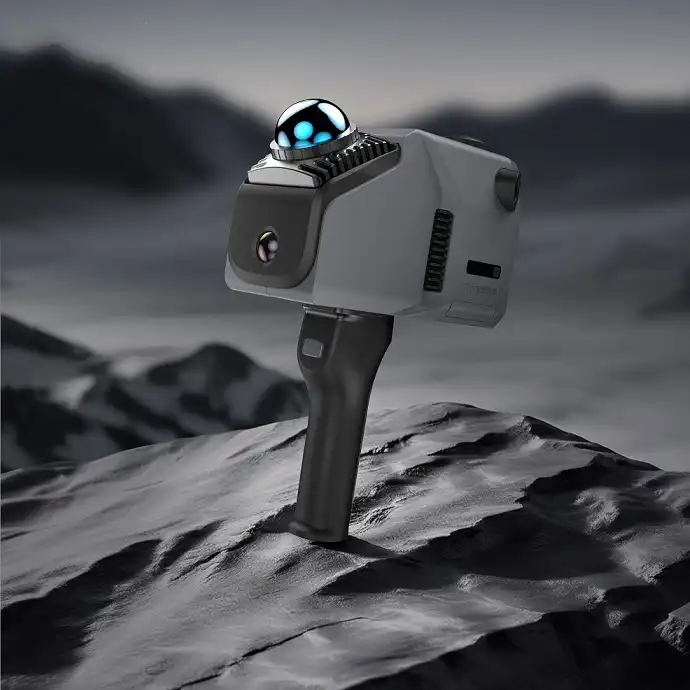
Selecting a battery pack for a LiDAR scanner is not the same as choosing a generic 12 V lead-acid or consumer power bank. A LiDAR head combines a rotating or oscillating mechanical assembly, a pulsed laser emitter, a detector and time-of-flight (ToF) electronics, an on-board compute unit, and a data radio or Ethernet link. That mix produces a load that swings between a low quiescent floor and short current peaks, operates outdoors across wide temperature ranges, and must stay light enough to carry, mount on a drone, or slide into a robot chassis. The three market tiers — 12 V, 14.4 V and 24 V — describe nominal system voltages, not a single cell count, and each tier maps to a different series configuration and chemistry. This note explains how the tiers are built, how to match a pack to real scanner platforms, what the battery management system (BMS) must protect against, how to size runtime, and which certifications matter before the pack ships.
1. Why LiDAR Scanners Demand a Purpose-Built Pack
A LiDAR scanner is a dynamic, mixed load rather than a constant resistor. During a scan session the current profile has three distinct phases, and a pack designed only for steady discharge will misjudge runtime and can brown out at the wrong moment.
1.1 A rotating load with current peaks
Mechanical multi-channel scanners spin their laser and receiver at several tens of revolutions per second. The motor draws a startup inrush several times its running current, and the laser pulser and compute board draw pulsed current superimposed on the average. A pack that is sized only to the nameplate average wattage can sag under the inrush, causing the scanner to reset or drop point-cloud frames exactly when coverage matters most.
1.2 Wide operating temperature and field portability
Mobile mapping, forestry, mining, construction survey and inspection are performed outdoors, often from below freezing to desert heat. Lithium cells lose usable capacity and effective voltage as temperature falls, and they age faster at sustained high temperature. A handheld or backpack unit also penalizes every gram, so energy density and pack weight are first-order design variables rather than afterthoughts.
1.3 Runtime continuity and hot-swap expectation
Survey crews cannot pause a scan to recharge in the field. Designs commonly rely on swappable battery cassettes, parallel redundancy, or a dock that keeps the head alive during a change. The pack must therefore support clean connection, controlled inrush on insertion, and accurate state-of-charge (SoC) reporting so the operator knows remaining minutes rather than a vague bar.
2. Decoding 12V / 14.4V / 24V: Series Configuration and Chemistry
The labels 12 V, 14.4 V and 24 V are market system names. The actual voltage is set by the number of cells in series (the S-count) and the cathode chemistry. Nickel-manganese-cobalt (NMC) cylindrical cells are commonly rated 3.6–3.7 V nominal, 4.2 V at full charge, and about 3.0 V at discharge cutoff; lithium iron phosphate (LiFePO4, LFP) cells are 3.2 V nominal, 3.65 V at full charge, and about 2.5 V at cutoff. Because the two chemistries have different nominal and charge voltages, a BMS matched to one cannot be swapped for the other.
Table 1. Common series configurations behind the 12 V / 14.4 V / 24 V market labels
| Market label | Chemistry & S-count | Nominal voltage | Full-charge voltage | Typical cutoff | Notes |
| 12 V | NMC 3S | 10.8–11.1 V | 12.6 V | ~9.0 V | Closest to a 12 V system; wide window covers 9–12 V heads |
| 12 V | LFP 4S | 12.8 V | 14.6 V | ~10.0 V | Stable 12.8 V rail; longer cycle life, lower energy density |
| 14.4 V | NMC 4S | 14.4 V (14.8 V at 3.7 V/cell) | 16.8 V | ~12.0 V | Common for handheld mobile-mapping scanners |
| 24 V | NMC 6S | 21.6–22.2 V | 25.2 V | ~18.0 V | Market ’24 V’; lower current for the same wattage |
| 24 V | LFP 8S | 25.6 V | 29.2 V | ~20.0 V | Heavy-duty, long-cycle 24 V-class rail |
A practical warning: a 4S NMC pack reaches 16.8 V at full charge, which sits above a nominal 12 V rail. If the scanner’s input tolerance does not cover that upper value, the system needs a regulated DC-DC stage or a charge set-point adjusted to the device window. Never assume the market label equals the device’s allowed input range; always read the scanner’s specified operating voltage window on its datasheet.
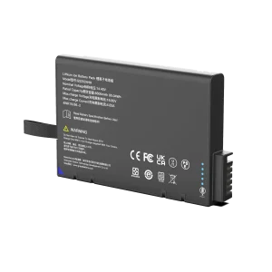
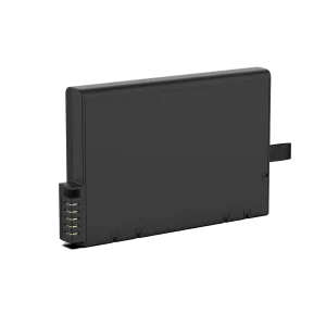
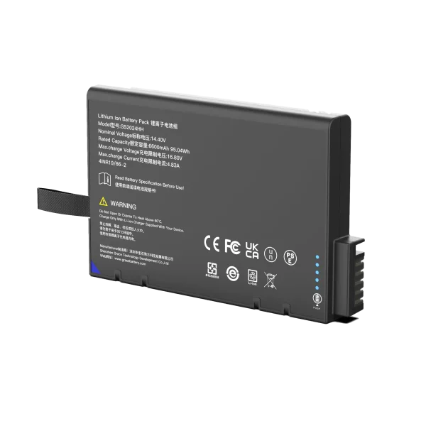
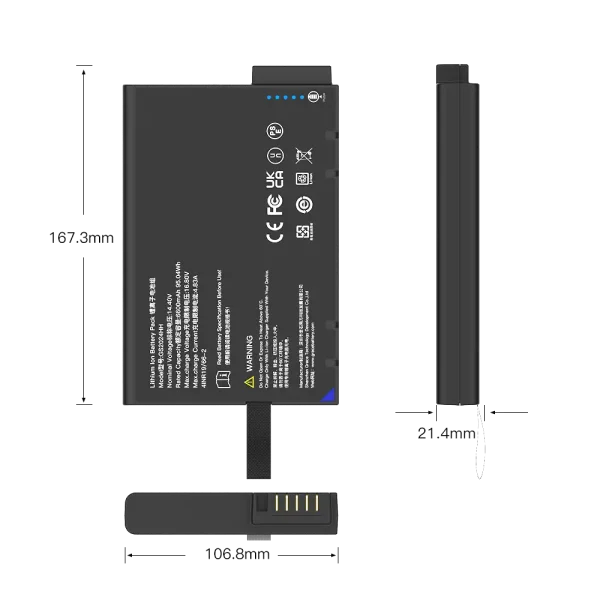
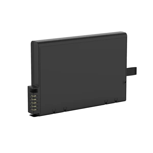
GS2024HH
14.4V/6900mAh/95.04Wh
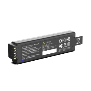
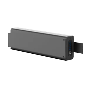
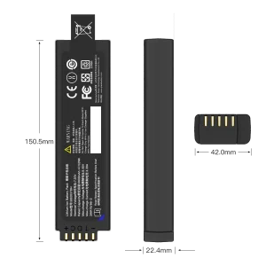
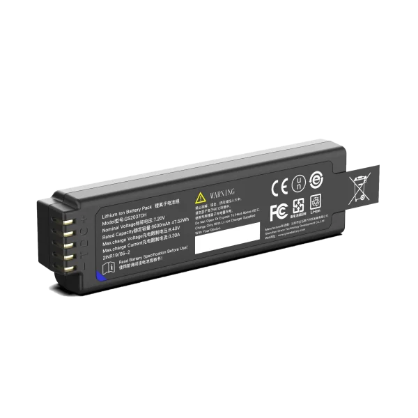
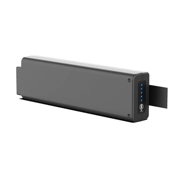
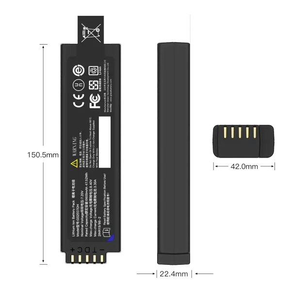
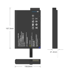
GS2037DH
7.2V/6900mAh/47.52Wh
3. Core Engineering Requirements for a LiDAR Battery Pack
3.1 BMS protection and cell balancing
The BMS must provide over-charge, over-discharge, over-current and short-circuit protection per cell group, with passive or active balancing to keep series cells within millivolts of each other. Without balancing, the weakest cell sets the pack’s usable capacity and reaches cutoff first, which is read by the host as an early empty. For a multi-cell handheld pack, cell-temperature sensing should feed charge inhibit below freezing and discharge derating at high temperature.
3.2 Voltage headroom, cable drop and inrush margin
Calculate the worst-case voltage at the device terminals, not at the pack. Add the ohmic drop across the harness and connector at peak current, and keep the lowest pack voltage under load above the device’s minimum input. Size continuous discharge current for at least 1.5–2 times the measured average, and confirm the BMS MOSFETs and fuse can absorb the motor inrush without tripping on a normal startup.
3.3 Smart fuel gauge and communication
A gauge (fuel-gauge IC with coulomb counting) reported over SMBus or I2C gives the host accurate remaining capacity, voltage, current, cell temperature and cycle count, instead of a raw open-circuit voltage that is unreliable under load. This is what lets the scanner display remaining scan time and supports orderly shutdown before deep discharge.
3.4 Thermal design and cold derating
Place temperature sensors near cells and the BMS power stage, use thermally conductive padding between cells and the enclosure, and specify a charge window that inhibits charging below about 0 °C to avoid lithium plating. Derate available capacity at low temperature in the runtime model rather than promising a full room-temperature figure in cold weather.
3.5 Mechanical, ingress and reliability
Handheld and rugged mounts expect drop, vibration and sealing. Specify an IP-rated enclosure appropriate to the environment, secure cell retention against 5 Hz–2 kHz vibration and shock, a latch or connector rated for repeated insertion, and a label showing Wh, nominal voltage, polarity and caution symbols.
4. Chemistry Selection: NMC vs LiFePO4
Choose between NMC and LFP against the dominant constraint of the use case — weight for handheld and drone, or cycle life and safety margin for fixed robot and cart platforms. Published chemistry comparisons place NMC cylindrical cells around 200–260 Wh/kg at the cell level and LFP around 120–160 Wh/kg[12], which is why NMC is preferred where every gram counts.
Table 3. NMC vs LFP for LiDAR support packs
| Attribute | NMC (3.6/3.7 V) | LiFePO4 (3.2 V) | Engineering implication |
| Cell energy density | ~200–260 Wh/kg at cell level | ~120–160 Wh/kg | NMC wins on light weight and compact size |
| Cycle life to 80% | Typically 500–1,500 cycles | Roughly 3,000–5,000+ cycles | LFP favors daily high-cycle fixed deployments |
| Nominal voltage | 3.6–3.7 V | 3.2 V | Changes S-count and BMS; not interchangeable |
| Thermal stability | Lower thermal runaway threshold | More stable cathode | LFP gives a wider safety margin in sealed enclosures |
| Best fit here | Handheld, backpack, drone payloads | Robot carts, fixed mount, long-shift stations | Match chemistry to weight vs longevity priority |
5. Sizing the Pack: Runtime Calculation
Size from energy, not from a guessed amp-hour figure. Use the scanner’s average power and target continuous session length, then apply bus efficiency and a depth-of-discharge (DoD) limit to preserve cycle life.
- Required pack energy (Wh) = (P_average × t_hours) ÷ (η_bus × DoD)
- Pack capacity (Ah) = Required Wh ÷ nominal pack voltage
Worked example: a 25 W average load, 2-hour target session, bus efficiency η = 0.92, and DoD = 0.90 give about 60.4 Wh; divided by a 14.4 V nominal rail this equals roughly 4.2 Ah, so a 4S pack rated 14.4 V / 5 Ah (with margin) is the practical choice. Re-run the calculation at the expected coldest temperature, where available capacity falls, and add a reserve for inrush and spare-session overhead.
6. Compliance, Certification and Air Transport
A pack sold into industrial and survey channels must clear safety, transport and market-entry requirements; these are checked by distributors, integrators and customs, not optional marketing badges. IEC 62133-2 defines safety requirements for portable sealed secondary lithium cells[10] and underpins CE marking, while UN 38.3 in the UN Manual of Tests and Criteria, Part III, subsection 38.3, is the mandatory transport test sequence before shipment[11].
- IEC 62133-2: safety requirements for portable sealed secondary lithium cells and batteries used in portable applications; it underpins CE marking and is recognized in CB Scheme routes to regional marks such as UL 62133 and Japan’s PSE.
- UN 38.3: the transport test sequence in the UN Manual of Tests and Criteria, Part III, subsection 38.3; lithium batteries that have not passed UN 38.3 cannot lawfully move by air, sea or road under most regimes, and test summaries must be available for the shipment.
- CE, RoHS and regional EMC/material restrictions apply to the finished pack; document cell origin, BMS scheme and test reports in the technical file.
- Air cabin threshold: spare lithium-ion batteries carried in passenger aircraft are generally limited to 100 Wh per cell/battery without airline approval; the 99.9 Wh rating on the BLK2FLY pack illustrates how payload designs sit just under this cabin threshold. Packs above 100 Wh (and up to 160 Wh) require carrier approval and remain carry-on only.
7. Selection Checklist for Integrators
- Read the scanner datasheet operating voltage window, maximum current and inrush before choosing the S-count; do not match on the market label alone.
- Confirm the BMS continuous and peak current, cutoff voltages and balancing scheme match the chosen chemistry and S-count.
- Budget cable drop and keep loaded terminal voltage above the device minimum; reserve headroom for startup inrush.
- Specify a coulomb-counting gauge on SMBus/I2C if the host expects SoC, temperature and cycle data.
- Size Wh from average power, session length, efficiency and DoD; derate for cold temperature.
- Match NMC to weight-critical handheld/drone use and LFP to long-cycle fixed platforms.
- Assemble IEC 62133-2, UN 38.3, CE/RoHS documentation and the Wh rating for transport before shipment.
8. Frequently Asked Questions
8.1 Is a 14.4 V pack the same as a 12 V pack?
No. A 14.4 V pack is typically a 4S NMC (14.4–14.8 V nominal, 16.8 V full charge), whereas a 12 V class may be a 3S NMC or a 4S LFP (12.8 V). The BMS and charge voltage differ, so they are not interchangeable without a regulated stage.
8.2 Why use 24 V for a high-power LiDAR instead of 12 V?
For the same wattage, 24 V draws half the current of 12 V, reducing cable heating, voltage drop and wire gauge. Multi-sensor hubs and drone payloads that reach 60–180 W favor 6S NMC or 8S LFP rails for that reason.
8.3 How long will a pack last in the field?
It depends on average watts and session length. Size energy from P × t divided by efficiency and DoD, then derate for cold; a rated amp-hour alone does not predict minutes under a dynamic scanning load.
8.4 Which certifications are mandatory before shipping?
UN 38.3 transport testing is a prerequisite for lawful shipment, and IEC 62133-2 supports safety compliance and market entry; CE/RoHS apply to the regional market. Verify the exact destination requirements with the importer before production.
About the Author
This note was prepared by a senior lithium-ion R&D engineer specializing in smart BMS-protected packs, SMBus/I2C fuel-gauge communication, and OEM custom battery systems for portable industrial instruments. Guidance reflects published manufacturer datasheets, international safety standards, and field experience sizing packs for dynamic motor-and-electronics loads; always validate final parameters against the specific scanner datasheet and destination regulations.
References
- GreenValley International, LiAir H800 UAV LiDAR System User Guide (supply 12–24 V, ≤61 W).
- Galaxy Electronic, TH-1320 product specification (DC 10–32 V, ≤5 W).
- DFRobot, RPLiDAR S2E ToF 360° Laser Range Scanner specification (9–28 V, ~200 mA @12 V, IP65).
- Hesai Technology, QT128C2X 128-Channel Mechanical LiDAR User Manual (DC 12–24 V, 12 W, −40 to 85 °C).
- Livox, Hub specifications (10–23 V DC, up to 180 W with five Mid-100 units).
- Velodyne Lidar, HDL-32E User Manual (9–32 VDC, 12 W typical, IP67).
- Leica Geosystems, BLK ARC technical specifications (nominal 12 V, 9–48 V, max 25 W).
- Leica Geosystems, BLK2FLY Autonomous Flying Laser Scanner spec sheet (14.8 V, 6.75 Ah, 99.9 Wh).
- GeoSLAM, ZEB Horizon User Guide v4.0 (14.8 V nominal, 0–40 °C operating).
- IEC 62133-2:2017, Secondary cells and batteries containing alkaline or other non-acid electrolytes — Safety requirements for portable sealed secondary lithium cells.
- UN Manual of Tests and Criteria, Part III, subsection 38.3 (UN 38.3); IATA Lithium Battery Guidance Document, 2020 edition.
- Cell Saviors, LFP vs NMC Lithium-Ion Battery Comparison (energy density); OneAndes, LiFePO4 vs NMC cycle-life comparison.