
A Senior R&D Engineer’s Guide to Powering GPR Instruments in the Field
1. Introduction
Ground Penetrating Radar (GPR) is a non-destructive geophysical method that uses high-frequency electromagnetic pulses to map subsurface structures. From locating rebar and conduits in concrete to detecting buried utilities, archaeological features, and voids beneath roadways, GPR systems have become indispensable tools in civil engineering, geology, archaeology, and infrastructure inspection. Unlike benchtop instruments, GPR units are deployed in the field—often in remote locations, extreme weather, and time-sensitive survey schedules. In this environment, the battery pack is not an afterthought. It is a mission-critical subsystem that directly determines survey productivity, data continuity, and total cost of ownership.
As a lithium battery engineer who has worked on custom power solutions for a range of portable industrial instruments, I have seen how often battery design is treated as a commodity procurement decision rather than an engineering partnership. The consequences are predictable: unexpected runtime drop-offs in cold weather, SoC estimates that drift away from reality, premature pack failure after a few hundred cycles, and last-minute certification delays that push product launches by quarters. This guide distills the key engineering decisions that go into a properly designed GPR battery pack, drawing on real-world system specifications and recognized industry standards.
2. Understanding GPR Power Requirements
Before specifying a battery pack, it is essential to understand how GPR systems consume power. Unlike continuous-load devices such as laptops, GPR instruments have a distinctive power profile: they draw relatively steady current for control electronics, display, and data storage, but deliver periodic high-current pulses to the radar antenna during transmission. This pulsed load behavior has direct implications for cell selection, BMS design, and runtime estimation.
2.1 Typical Voltage Architectures
The majority of portable and cart-based GPR systems on the market today operate at 11.1 V nominal (3S lithium-ion configuration) or 12 V nominal. For example, the Zond Aero 500 NG system uses a 3S3P 18650 pack rated at 11.1 V and 9.0 Ah. The ImpulseRadar PinPointR is powered by a removable 8.7 Ah / 96.57 Wh Li-ion pack at roughly 12 V. Some higher-end systems may use 14.8 V (4S) architectures, but the 3S platform remains the dominant form factor for handheld and backpack GPR units.
2.2 Power Consumption and Runtime
Typical GPR power consumption ranges from 15 W to 25 W during active data acquisition. Reference specifications from leading manufacturers put the operating current at approximately 1.26–1.5 A at 12 V. At this draw rate, a 96 Wh battery pack delivers roughly 6–7 hours of continuous operation, which aligns with the advertised ~7-hour runtime of the ImpulseRadar PinPointR. Compact handheld units like the GSSI FlexNX, which integrates a 2.5 GHz antenna and 7-inch touchscreen into a 2.2 kg body, are rated at approximately 3 hours on its internal battery—a useful benchmark for battery capacity sizing in self-contained GPR designs.
Table 1. Representative GPR System Battery Specifications
| GPR System | Nominal Voltage | Battery Capacity | Typical Runtime |
| ImpulseRadar PinPointR | ~12 V | 8.7 Ah / 96.57 Wh | ~7 hours |
| Zond Aero 500 NG | 11.1 V (3S) | 9.0 Ah | ~6 hours |
| GSSI FlexNX | Internal Li-ion | Integrated | ~3 hours |
| Typical Cart-Mounted GPR | 12 V | 7–10 Ah | 4–8 hours |
These figures are reference points, not universal values. Actual runtime depends on scan rate, antenna frequency, display brightness, GPS usage, wireless data transfer, and ambient temperature. A well-engineered battery pack should be sized with at least a 20% safety margin above the manufacturer’s nominal consumption to account for cold-weather derating and end-of-life capacity fade.
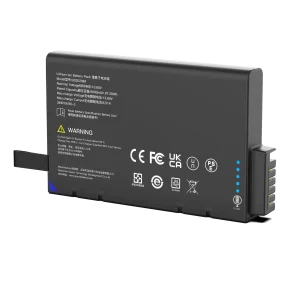
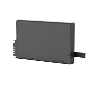
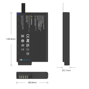
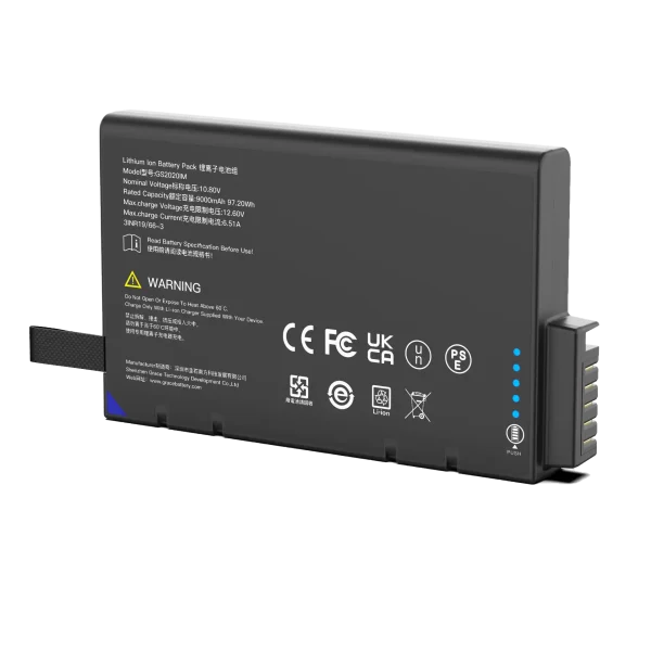
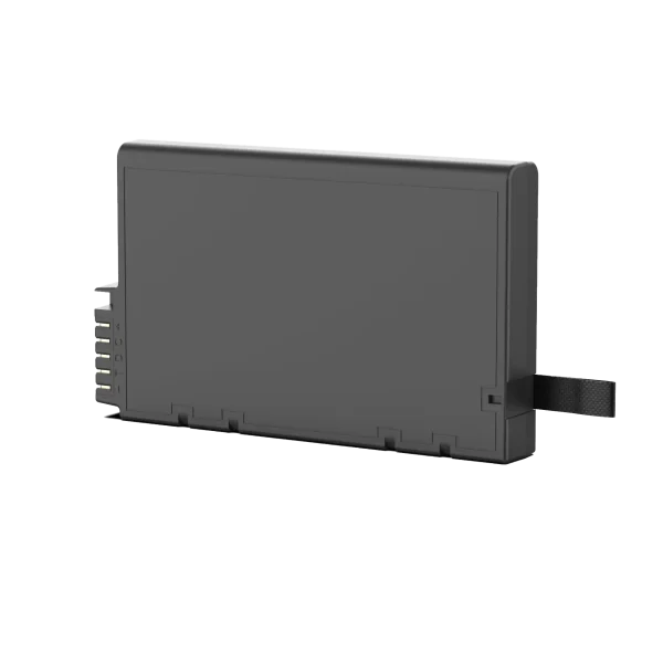
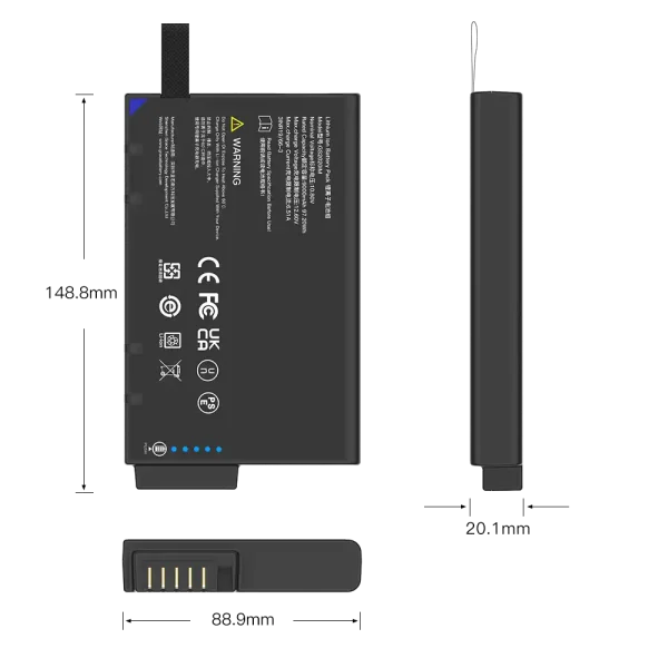
GS2020IM
10.8V/9300mAh/97.2Wh
3. Critical Design Considerations for GPR Battery Packs
GPR battery packs operate in environments that consumer electronics never encounter: dust, rain, mud, extreme temperatures, vibration from vehicle towing, and frequent drop impacts. Designing a pack that survives these conditions requires deliberate choices across multiple dimensions.
3.1 Energy Density and Runtime Optimization
For handheld and backpack GPR units, weight and runtime are in direct tension. Every additional 100 grams of battery adds to surveyor fatigue over a full workday. The engineering goal is to maximize usable watt-hours per kilogram without sacrificing cycle life or safety. Nickel Manganese Cobalt (NMC) chemistry typically delivers 250–280 Wh/kg at the cell level, making it the preferred choice for portable GPR where weight is the primary constraint. For cart-mounted systems where weight matters less, LiFePO4 may be preferred for its longer cycle life and thermal stability.
3.2 Wide Operating Temperature Range
GPR surveys are conducted everywhere from sub-zero winter road inspections to desert archaeological digs. A GSSI FlexNX is specified to operate from -20 °C to +50 °C, and a properly engineered battery pack must match that envelope. Lithium-ion chemistry loses available capacity and internal resistance rises sharply at low temperatures. At -20 °C, a typical NMC pack may deliver only 60–70% of its rated capacity. Design mitigations include selecting low-temperature-grade cells, incorporating heating elements where enclosure volume permits, and derating runtime expectations in cold-weather spec sheets rather than overpromising.
3.3 Environmental Sealing and Durability
Outdoor GPR equipment is commonly rated IP65 or better against dust and water ingress. The battery pack, whether internal or removable, must meet or exceed this rating. Removable packs introduce additional sealing challenges at the connector interface. Common design choices include O-ring sealed enclosures, overmolded connectors, and conformal coating on the PCB. Shock and vibration standards for field gear typically follow MIL-STD-810 or IEC 60068 benchmarks, and the pack must be drop-tested from at least 1.0 m onto a concrete surface without enclosure rupture or safety risk.
3.4 Hot-Swap and Spare Battery Workflow
Professional survey crews routinely carry spare batteries to maintain productivity across long shifts. A well-designed GPR battery system supports hot-swap operation—allowing the user to swap packs without shutting down the GPR unit and losing in-memory data. This requires the BMS to maintain a clean voltage output during handoff and the GPR host to have sufficient bulk capacitance to bridge the swap interval. Mechanical design must also make battery swaps quick and tool-free, ideally with a latch mechanism that can be operated while wearing gloves.
4. Chemistry Selection: Choosing the Right Cell for GPR
Cell chemistry is the foundation of every battery pack design. There is no single “best” chemistry for GPR; the correct choice depends on the system’s form factor, weight budget, expected cycle life, and operating environment.
Table 2. Lithium Chemistry Comparison for GPR Applications
| Chemistry | Energy Density | Cycle Life | Thermal Safety | Best Fit |
| NMC (NCM) | High (250–280 Wh/kg) | 500–1,000 cycles | Moderate | Handheld / backpack GPR |
| LiFePO4 (LFP) | Moderate (120–160 Wh/kg) | 2,000–4,000 cycles | Excellent | Cart-mounted / vehicle GPR |
| LCO | High (200 Wh/kg) | 300–500 cycles | Lower margin | Compact embedded units |
| NCA | Very high (260–300 Wh/kg) | 300–500 cycles | Moderate | Ultra-lightweight custom builds |
4.1 NMC: The Workhorse of Portable GPR
Nickel Manganese Cobalt (NMC) is the most common chemistry in portable GPR battery packs. Its high specific energy allows engineers to fit meaningful runtime into a compact, lightweight enclosure. NMC cells are available in standard 18650 and 21700 form factors from a broad supplier base, which reduces sourcing risk and cost. The trade-off is moderate cycle life—typically 500 to 1,000 cycles to 80% capacity—meaning that a heavily used GPR battery may need replacement every 1–2 years. For most field service workflows, this is an acceptable trade-off for the weight savings.
4.2 LiFePO4: Long-Life for Stationary and Cart Systems
Lithium Iron Phosphate (LiFePO4) trades energy density for exceptional cycle life and thermal stability. Where a GPR unit is cart-mounted or vehicle-towed and weight is not the primary constraint, LiFePO4 packs deliver 2,000–4,000 cycles and a much wider safe operating temperature window. LiFePO4 chemistry is also less prone to thermal runaway, which is a meaningful safety consideration for equipment transported in survey vehicles. The lower nominal voltage (3.2 V per cell) means a 4S LiFePO4 pack yields 12.8 V nominal, which is compatible with most 12 V GPR systems with appropriate DC-DC regulation.
5. BMS: The Intelligence Behind Every Reliable GPR Pack
A battery pack without a well-designed Battery Management System (BMS) is just a bag of cells with exposed terminals. The BMS is the embedded controller that monitors, protects, and communicates the pack’s state to the host device. In GPR applications, where accurate runtime estimation directly affects survey planning, BMS quality is not a secondary concern—it is central to the user experience.
5.1 Core Protection Functions
Every production-grade BMS must enforce a baseline set of safety protections: overcharge protection (cutoff when any cell exceeds the upper voltage threshold), over-discharge protection (preventing deep discharge that damages cells), overcurrent protection (responding to load short circuits or abnormal current draw), and over-temperature protection (shutting down charge or discharge when cell temperature exceeds safe limits). For GPR equipment, which may be left in survey vehicles under hot sun, the BMS should also support storage-mode functionality that drops the pack to a safe state-of-charge for long periods of inactivity.
5.2 SMBus Communication and Host Integration
Modern GPR systems rely on real-time battery data displayed on the user interface: state of charge (SoC), pack voltage, remaining runtime estimate, and temperature. This data exchange typically runs over the System Management Bus (SMBus), a two-wire serial protocol derived from I2C. A smart GPR battery pack with SMBus support reports fuel-gauge data directly to the GPR host, eliminating the need for crude voltage-based SoC estimation that drifts significantly across temperature and cycle life. At TEFOO, our custom BMS firmware is tailored to the GPR load profile—including pulsed discharge characteristics—for more accurate remaining-run time predictions than generic off-the-shelf BMS boards can deliver.
5.3 Cell Balancing and Pack Longevity
Series-connected cells in a pack drift in capacity and internal resistance over hundreds of cycles. Without cell balancing, the weakest cell determines the pack’s usable capacity, leading to premature runtime degradation. Passive balancing—where excess charge on stronger cells is dissipated as heat—is cost-effective and adequate for most GPR pack sizes (3S to 4S configurations). Active balancing, which transfers energy between cells, adds complexity and cost but is worth considering for larger multi-cell configurations where pack longevity is a premium feature.
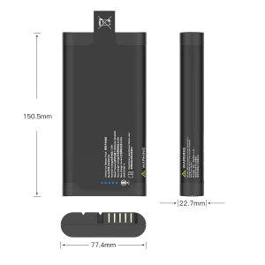
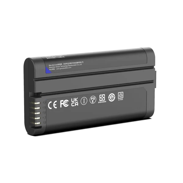
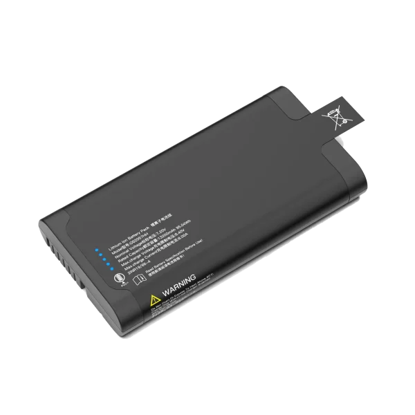
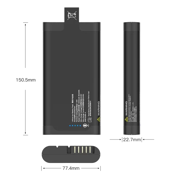
GS2057HH
7.2V/13800mAh/95.04Wh
6. Compliance and Certification Landscape
A GPR battery pack that cannot be shipped, sold, or serviced in the target market is a design failure, regardless of how well it performs electrically. Certification is not a final-stage checkbox; it must be designed into the pack from the beginning, because test failures discovered late in the process often require mechanical or electrical redesign.
Table 3. Key Certifications for GPR Battery Packs
| Certification | Scope | Why It Matters for GPR |
| UN 38.3 | Transport safety for lithium batteries (air, sea, road) | Mandatory for shipping GPR batteries worldwide; 8-test protocol includes altitude, thermal, vibration, shock, short circuit, overcharge, and forced discharge. |
| IEC 62133-2 | Safety requirements for portable sealed lithium cells | Recognized by global certification bodies; covers cell-level and pack-level safety design. |
| CE Marking | EU conformity (EMC + LVD directives) | Required for selling GPR equipment and batteries in the European Economic Area. |
| FCC Part 15 | US electromagnetic compatibility (Subpart J covers UWB imaging) | GPR is classified as UWB imaging equipment; the battery subsystem must not introduce interference. |
| EU 2023/1542 | New EU Battery Regulation | Imposes carbon footprint, recycled content, and due-diligence obligations on battery manufacturers. |
| ISO 9001 / 14001 | Quality management and environmental management systems | Evidence of controlled manufacturing processes expected by enterprise GPR OEM customers. |
UN 38.3 deserves special emphasis because it is the most commonly overlooked requirement in rushed product launches. The standard defines eight test conditions—altitude simulation, thermal test, vibration, shock, external short circuit, impact/crush, overcharge, and forced discharge—that every lithium battery pack must pass before it can be transported by air, sea, or road. A pack that has not completed UN 38.3 testing cannot be legally shipped across international borders, which effectively blocks any GPR OEM serving a global customer base.
7. The OEM Custom Battery Pack Design Process
For GPR OEMs seeking a battery pack tailored to their specific instrument, a structured development process de-risks the program and shortens time-to-market. Based on our experience delivering custom battery solutions for industrial instruments, here is the framework we follow at TEFOO.
Step 1: Requirements Definition
The process begins with a detailed requirements document: target voltage and capacity, mechanical envelope and mounting interface, communication protocol (SMBus / I2C / CAN), connector type, operating and storage temperature ranges, IP rating, expected cycle life, and target certifications. The more precise this front-end specification, the fewer design iterations later.
Step 2: Cell Selection and Electrical Architecture
Based on the requirements, we select the optimal cell chemistry and form factor (18650, 21700, prismatic, or pouch). We then define the series/parallel configuration, estimate pack-level energy density, and model expected runtime against the GPR system’s power profile. Protection FET ratings, fuse selection, and BMS IC selection are determined at this stage.
Step 3: BMS Firmware Customization
The BMS firmware is configured to the GPR application: protection thresholds tuned to the chosen cells, SMBus slave address and register map matched to the GPR host expectations, SoC algorithm calibrated for the discharge profile of a pulsed radar load, and low-temperature charge/discharge derating curves. This is where generic battery packs fall short—they use one-size-fits-all fuel gauge algorithms that do not account for the unique load characteristics of GPR systems.
Step 4: Mechanical Design and Prototyping
The enclosure is designed for the target IP rating, drop performance, and thermal dissipation. A functional prototype is assembled and bench-tested for capacity, runtime, charge cycle, and communication reliability. Environmental and mechanical testing follows—temperature chambers, vibration tables, and drop tests—before the design is locked for certification.
Step 5: Certification and Production Ramp
Once prototypes pass internal validation, the pack enters the formal certification queue: UN 38.3, IEC 62133, CE, and any market-specific requirements. Parallel to certification, production test fixtures and quality control processes are established. At TEFOO, our ISO 9001-certified manufacturing line supports production volumes from small pilot runs to mass production, with full traceability from cell lot to finished pack.
8. Frequently Asked Questions
Q1: How long should a GPR battery last on a single charge?
A typical professional-grade GPR battery pack delivers 4 to 8 hours of continuous operation, depending on system class. Compact handheld units may be rated at 3 hours, while larger cart-mounted systems with 10 Ah packs can exceed 8 hours. For survey planning, we recommend assuming 70–80% of the advertised rating in cold weather and at end-of-life capacity, and carrying at least one spare pack per surveyor.
Q2: Can I use a third-party battery instead of the OEM pack?
Functionally, a third-party pack with matching voltage, connector, and communication protocol may power the GPR unit. However, there are important caveats: the fuel gauge and SoC display may not work correctly if the SMBus register map does not match, and uncertified packs may not meet the safety and transport standards that the OEM warranty and regulatory approvals depend on. For mission-critical work, an OEM or qualified custom pack is the safer long-term investment.
Q3: What temperature range can GPR batteries handle?
Most commercial GPR systems specify an operating range of -20 °C to +50 °C. The battery pack should match or exceed this range. In practice, cold temperatures reduce both available capacity (down to 60–70% at -20 °C for NMC cells) and allowable charge current. A well-designed BMS will enforce charge-only-when-warm rules to prevent lithium plating and permanent cell damage.
Q4: Is UN 38.3 certification really necessary?
Yes—without UN 38.3, lithium battery packs cannot legally be transported by air, sea, or most road freight carriers. GPR OEMs selling globally cannot ship their instruments with uncertified batteries. For replacement and spare packs sold in the aftermarket, UN 38.3 certification is equally essential and is a basic indicator that the pack has passed a minimum set of safety tests.
Q5: How does SMBus benefit GPR battery integration?
SMBus allows the GPR host to read real-time pack data: voltage, current, temperature, state of charge, and cycle count. This enables accurate runtime prediction, intelligent low-battery warnings, and diagnostic visibility into battery health over time. GPR systems without SMBus integration fall back to estimating SoC from open-circuit voltage alone, which is notoriously inaccurate across different load profiles and temperatures.
9. Conclusion
A GPR battery pack is far more than a standardized power accessory. It is an engineered subsystem whose chemistry, BMS intelligence, ruggedness, and certification directly impact survey productivity, data quality, and the total cost of ownership of the entire GPR instrument. The most reliable GPR deployments are those where the battery pack was designed in parallel with the instrument itself—not selected from a catalog as an afterthought.
At TEFOO Energy, we specialize in custom lithium battery packs for portable industrial and instrumentation equipment, including GPR and other geophysical survey instruments. Our engineering team brings deep experience in smart BMS design, SMBus integration, thermal optimization, and full certification support—from UN 38.3 and IEC 62133 to CE, FCC, and the latest EU 2023/1542 requirements. If you are developing a new GPR platform or optimizing an existing product line, we invite you to start the conversation early: the best battery pack is the one designed with your system, not for it.