1. Introduction: The Power Behind the Analysis
In field applications, a handheld XRF analyzer must deliver laboratory-quality results from a device held in one hand. The measurement chain — an X-ray tube driven at tens of kilovolts, a silicon-drift or PIN detector, pulse-processing electronics and an embedded computer — consumes far more power during a measurement than during standby, and it does so in short bursts, hundreds of times per working day.
As a lithium battery R&D engineer who has designed power systems for portable analytical instruments, I have watched battery packs be treated as interchangeable accessories — and then watched field returns tell a different story: premature capacity loss, thermal shutdowns on hot job sites, sudden power loss in the middle of a measurement, and transport-documentation gaps. This article is written to help product engineers, procurement teams and OEMs specify and validate battery packs that perform as well as the instruments they power.
2. The XRF Load Profile That Defines the Battery
2.1 Why handheld XRF is hard on batteries
Three characteristics of the XRF application dominate battery design:
- Pulsed, not steady, load. Every measurement fires the X-ray tube. The high-voltage generator charges the tube and the instrument draws a burst of power — typically in the tens of watts — for the duration of the analysis, then returns to a low-power idle. The battery must hold its terminal voltage within the analyzer’s operating window during these transients, including at low state of charge (SOC) and low temperature.
- Duty cycle sets the energy budget. An alloy-sorting operator may trigger a measurement every few seconds for hours; a survey user may take readings minutes apart. Average power — the product of measurement power and duty cycle, plus idle power — determines runtime. A pack sized for peak power alone is unnecessarily heavy; a pack sized for average power alone may sag under load.
- Cold starts and warm-ups. Tube warm-up and high-voltage conditioning pull current at the very start of a measurement sequence. If the pack is cold or partially discharged, its internal resistance is higher and the voltage sag is deeper — a common root cause of unexplained instrument resets.
- The host needs data, not just electrons. Modern analyzers read battery telemetry — remaining capacity, voltage, temperature and health — over a digital bus and warn the operator before shutdown. A pack with only a protection board cannot support this, which is why smart packs are the norm in this class of instrument.
2.2 A typical measurement cycle
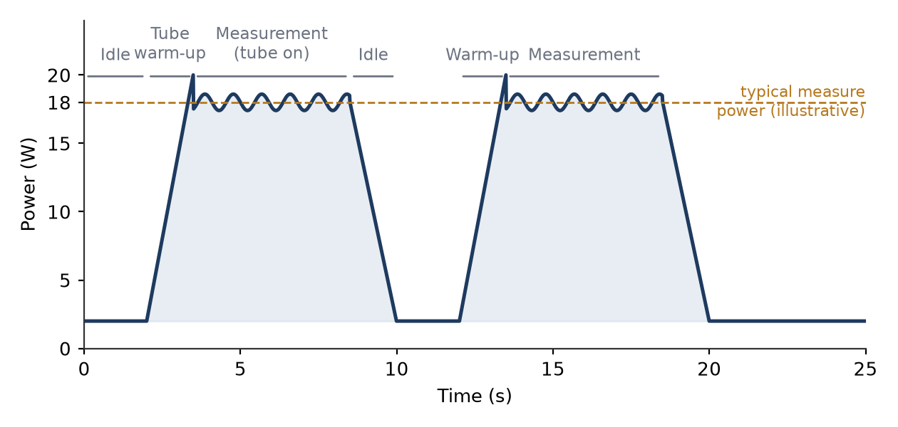
Figure 1 shows an illustrative power profile for one measurement cycle. The analyzer idles at roughly 2 W, ramps up during tube warm-up to about 18–20 W, holds a measurement plateau near 18 W with ripple from the high-voltage inverter, and drops back to idle. Exact values depend on tube power, anode voltage, detector settings and measurement time; the shape is what matters for battery design.
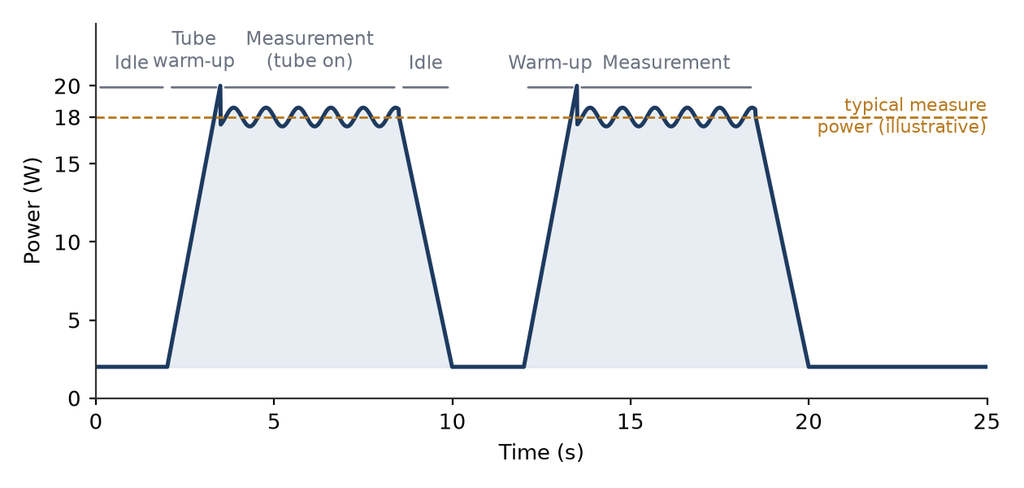
Figure 1. Illustrative handheld XRF measurement-cycle power profile (typical values vary by analyzer model and measurement settings).
A sizing sanity check illustrates the point. At a 30 % duty cycle, an 18 W measurement load and a 2 W idle give an average power of about 7 W. On a 52 Wh pack — for example 7.4 V × 7.1 Ah — roughly 80 % usable energy yields about six hours of such a working pattern, before any margin for cold temperature, aging or battery self-consumption. The duty-cycle assumption changes the answer more than the peak power does, which is why a serious battery supplier will ask about the measurement pattern before quoting a capacity.
2.3 Reference points from commercial instruments
It is instructive to look at how established instruments are actually powered. Table 1 summarizes three commercial platforms.
Table 1. Commercial handheld XRF analyzers and their battery platforms (data from the cited product documents).
| Analyzer | Battery type | Nominal voltage | Capacity | Notes | Source |
| Thermo Scientific Niton XL2 Plus | Li-ion pack | 7.4 V DC | 7.1 Ah | Charger: 12 V DC, 3 A | Thermo DoC, 2026 |
| Thermo Scientific IonicX | Li-ion pack | 12 V | — | 1.3 kg without test stand | Thermo datasheet |
| Evident Vanta (Max / Core) | Removable Li-ion | 14.4 V | — | Hot-swap on Max; 4 W, 8–50 kV tube; pack about 230 g | Evident product page |
The Thermo Scientific Niton XL2 Plus, for example, uses a 7.4 V DC lithium-ion pack rated at 7.1 Ah[6], charged from a 12 V DC supply. The IonicX runs on a 12 V lithium-ion battery[7], and the Evident Vanta family uses a removable 14.4 V Li-ion pack, with hot-swap capability on the Max series[8]. Pack voltage tracks the analyzer’s internal power architecture rather than a battery-industry preference, and the same engineering discipline is needed at 7.4 V as at 14.4 V.
3. Cell and Pack Architecture
3.1 Series configuration and nominal voltage
Lithium-ion cells are connected in series to reach the bus voltage the analyzer needs. Two cells (2S) give 7.4 V nominal, three (3S) give 11.1 V, and four (4S) give 14.4 V — the platforms seen in the instruments above. A higher bus voltage lowers the current required for a given power, reducing resistive losses and wire gauge; it also adds cells to balance and protect. The choice belongs to the instrument architect, and the battery engineer must implement it reliably.
Energy capacity in this class typically spans roughly 25–110 Wh depending on platform and mission. Cells are paralleled to raise capacity; the series-to-parallel ratio determines both voltage and energy, and the pack must fit the instrument’s volume and weight budget while still dissipating heat.
3.2 Cell chemistry and form factor
High-energy cylindrical cells — 18650 and, increasingly, 21700 — dominate handheld XRF packs. NMC and NCA chemistries provide the energy density (on the order of 250 Wh/kg at cell level for current high-energy products) needed to keep instrument weight acceptable, and high-rate variants provide the pulse capability. Pouch cells appear when a thin pack is mandatory, but they are less common in rugged handhelds because of mechanical and thermal constraints.
Cell selection is an engineering trade among energy density, pulse capability, internal-resistance growth, cost and availability. Every number must come from the cell manufacturer’s datasheet and qualification data — capacity, impedance, cycle life and temperature limits — and cells must remain traceable by lot for field quality follow-up.
3.3 Energy, weight and ergonomics
Battery weight is a first-class ergonomics problem. The Vanta Max, for instance, weighs 1.90 kg with its battery and 1.67 kg without — the pack is about 230 g of an instrument that must be aimed one-handed for long periods. Adding capacity adds weight, so the right point is found in field trials, not on a datasheet. Hot-swappable designs add a docking interface and require the analyzer to maintain power during the exchange; the pack must also survive thousands of insertion and removal cycles.
4. Mechanical and Thermal Design
4.1 Drop, vibration and environmental ingress
Field instruments get dropped. The battery must survive the same drop heights and orientations as the instrument, and the drop regime should be agreed with the analyzer OEM and executed on representative packs. Connector strain relief, cell anchoring inside the frame and solder-joint robustness matter more than case thickness alone.
Vibration — from transport and from hand-held use — can fatigue cell tabs, connectors and solder joints over thousands of cycles. Rigid PCB potting, preloaded cell stacks and strain-relieved cable exits are the usual countermeasures. Rugged analyzers are typically rated against dust and moisture ingress, and the pack enclosure should carry an equivalent rating with gasketed access, because the pack is the part most often opened by a technician.
4.2 Thermal management under continuous measurement
Two heat sources meet inside the pack: internal resistive heating from measurement pulses, and heat conducted back from the instrument. Under continuous operation the pack temperature rises, and the BMS must derate, warn, or — in a worst case — disconnect. Thermistors must measure the hottest cell, not the coolest spot on the PCB.
Handheld packs have no fan, so thermal design is passive: an aluminum frame acting as a heat spreader, thermal interface material to the analyzer body, and careful placement of the high-dissipation cells. Typical operating windows for Li-ion cells are 0–45 °C for charging and roughly −20 to 60 °C for discharge, but the real limits come from the cell datasheet. At low temperature the available pulse power drops sharply, and a good gauge reports capability, not just SOC.
5. Smart BMS: Engineering the Brain of the Pack
5.1 Protection layer
A BMS for this application has three jobs: protect the cells, measure their state, and communicate with the host. Protection is implemented in hardware and firmware — per-cell over-voltage and under-voltage, discharge over-current, short circuit, over-temperature and under-temperature — usually with a redundant path, so that an analog front end (AFE) acts independently of the microcontroller. Table 2 lists typical protection thresholds used as design targets.
Table 2. Typical BMS protection thresholds (design targets, not a standard).
| Protection | Typical design target | Response |
| Cell over-voltage | 4.25–4.30 V per cell | Stop charge |
| Cell under-voltage | 2.50–2.80 V per cell | Stop discharge |
| Discharge over-current | 2–3 × continuous rating | FET off, latch or auto-recovery |
| Short circuit | Immediate | FET off, latch |
| Charge over-temperature | 45–50 °C | Stop charge |
| Discharge over-temperature | 60–65 °C | Derate or stop discharge |
| Charge under-temperature | 0 °C | Stop charge |
Values are typical design targets; validate them against the selected cell’s datasheet and the project’s safety requirements.
Protection FETs are chosen for low on-resistance — a 30 mΩ pair at 5 A dissipates 0.75 W, which matters in a 50 Wh pack. The BMS must also handle cold-start inrush: an aggressive current limit can trip the pack at the very moment the analyzer is trying to start a measurement.
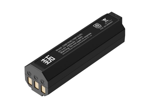
GSB1S38
3.6V/3450mAh/11.88Wh
5.2 Fuel gauging and SMBus telemetry
An accurate fuel gauge is what separates a smart pack from a protected one. Coulomb counting integrates current, but drift must be corrected against open-circuit voltage and cell impedance, which change with temperature, age and load. A good gauge also tracks the effect of the XRF pulse load — precisely the kind of high-rate event that naive integration gets wrong. Figure 2 shows the typical architecture.
Figure 2. Smart battery pack architecture: cell stack, analog front end, microcontroller with fuel gauge, and SMBus/I2C telemetry to the host.
The system communicates over the System Management Bus (SMBus), which is the de facto interface for smart batteries[9]. The Smart Battery Data Specification defines the standard command set[10] — remaining capacity, voltage, current, temperature, cycle count and design capacity, among others — so the analyzer can display real runtime, warn before shutdown, and record battery history for diagnostics.
5.3 Balancing and self-discharge management
Cells in series age differently. Passive balancing during charging — typically near the top of charge, with currents in the tens of milliamperes — keeps the stack healthy over hundreds of cycles. Packs also spend long periods in storage, so the BMS must minimize self-consumption: a sleep mode drawing microamperes, wake on button or charge connection, and a ship mode that places the pack under minimal load during logistics.
5.4 Firmware safety state machine and calibration
The firmware runs a safety state machine — normal operation, protection events with latching or auto-recovery rules, and recovery — and every event is logged with a timestamp in non-volatile memory so that field returns can be diagnosed. Gauging accuracy also depends on calibration: full-charge/full-discharge learning cycles, impedance updates and capacity-drift compensation. When a pack is replaced in the field, the analyzer should re-learn the new pack’s parameters rather than inherit the old ones.
6. Charging Interfaces and Charger Design
Lithium-ion packs charge with a constant-current/constant-voltage (CC–CV) profile, typically at 0.5 C with a termination current around 5–10 % of rated current, giving a charge time of roughly 2.5–4 hours at moderate temperature. The charger must match the pack voltage; the Niton XL2 Plus, for example, ships with a charger rated 12 V DC / 3 A[6].
Charging is temperature-gated by the BMS — disabled below 0 °C and above the cell’s upper charge limit — and the connector must survive years of field plugging; keyed or magnetic connectors are common. USB-C power delivery is an attractive direction for reducing accessory count, but the pack must then implement the power negotiation while still exposing the same smart-battery telemetry.
7. Safety, Compliance and Certification
7.1 Applicable standards and regulations
A battery pack is a regulated component, and the standards that apply depend on where the analyzer is sold and how the pack travels. Table 3 lists the principal instruments.
Table 3. Principal safety and transport standards for an XRF battery pack.
| Standard | Scope | Relevance to an XRF battery pack |
| IEC 62133-2:2017 | Safety of portable sealed secondary cells and batteries, lithium systems | Baseline cell and small-pack safety for portable applications |
| IEC 62619:2022 | Safety of secondary lithium cells and batteries for industrial applications | Covers packs for industrial and analytical equipment |
| GB 31241-2022 | China mandatory safety specification for lithium cells and batteries in portable electronics | Required for products sold and used in China |
| UN 38.3 (Manual of Tests and Criteria, Section 38.3) | Transport tests for lithium cells and batteries | Required for road, sea and air transport |
| IEC 62368-1:2023 | Safety of audio/video, information and communication technology equipment | End-equipment safety, including battery enclosure and charging |
IEC 62133-2:2017 is the baseline cell and pack safety standard for portable applications[1]. IEC 62619:2022 covers secondary lithium cells and batteries for industrial equipment[2]. GB 31241-2022 is the mandatory safety specification for lithium cells and batteries in portable electronic products[3]. For the instrument as a whole, IEC 62368-1:2023 addresses safety of the end equipment, including its battery enclosure and charging interfaces[5].
7.2 What compliance really requires
Transport is where lithium batteries receive the most scrutiny. Under the UN Manual of Tests and Criteria, Section 38.3, eight transport tests (T1–T8)[4] must be passed: altitude simulation (T1), thermal cycling (T2), vibration (T3), shock (T4), external short circuit (T5), impact/crush (T6), overcharge (T7) and forced discharge (T8). The tests run on production-representative cells and packs, and a test summary must accompany every shipment.
For air cargo, lithium-ion cells and batteries shipped on their own must be at no more than 30 % state of charge[11] unless the States concerned approve a higher value (Special Provision A331). In practice this means packs are shipped partially discharged, and the ship-mode feature of the BMS is a logistics requirement, not a convenience.
On the product side, the analyzer carries the CE marking and market-specific marks (for example UL for North America, CCC for China); the battery is a component of that assessment and must carry its own certificates for the markets in question. Ask for current certificates — a certificate issued against a superseded standard edition is not evidence of compliance.
8. Validation from an Engineering Point of View
8.1 Design validation matrix
Certification tests are the floor, not the ceiling. An OEM should additionally require design validation on the actual pack. Table 4 summarizes a typical matrix; acceptance criteria are project-specific and should be written into the specification before the program starts.
Table 4. Design validation matrix (typical; acceptance criteria are project-specific).
| Area | Representative tests | Typical acceptance (design target) |
| Electrical | Capacity at 0.2C and 0.5C; protection-trigger verification; charge/discharge across temperature | Capacity at or above rating; thresholds within tolerance |
| Mechanical | Drop per instrument specification; vibration; connector durability | No damage; no loss of function |
| Thermal | Thermal cycling; low-temperature pulse; high-temperature derating | No venting; voltage stays within window |
| Life | Cycle life (for example 500 cycles); calendar aging | At least 80 % capacity retention (target) |
| Transport and abuse | UN 38.3 T1–T8; overcharge and external short circuit per IEC 62133-2 / IEC 62619 | No fire; no explosion |
Pulse capability deserves a dedicated test: replay the measurement waveform of the actual analyzer at low SOC and at the low-temperature corner while recording voltage sag and gauge accuracy. This is the test that reveals whether the pack is truly matched to the instrument.
8.2 Field reliability and returns analysis
After launch, the data loop closes. Logged cycle counts, capacity fade, impedance growth and temperature exposure tell you how the pack is aging in real use. Field-return analysis should categorize every failure — mechanical damage, connector wear, cell imbalance, firmware edge cases — and feed the findings back into the design FMEA and the next firmware revision. In our experience, a surprisingly large share of battery failures turn out to be gauge drift or a worn connector rather than a dead cell, and the smart pack’s logs are the fastest way to tell the difference.
9. Maintenance, Storage and End of Life
Storage. Keep the pack between roughly 30–50 % SOC in a cool, dry place and recharge periodically — a common recommendation is every 3–6 months, depending on self-discharge and temperature. Storing a pack fully charged or fully discharged accelerates aging.
Shipping. Discharge to the transport SOC before air shipment and place the pack in ship mode. Verify the current UN 38.3 test summary and the shipper’s declaration with your logistics partner.
End of life. Plan replacement when capacity falls below about 80 % of rated capacity, or when the pack shows swelling, abnormal voltage spread between cells, or a persistent thermal warning. Dispose of packs through certified recyclers in accordance with applicable local regulations, and recalibrate the analyzer’s fuel-gauge parameters after replacing the pack.
10. How to Qualify a Battery Partner
The engineering bar above only works if the supplier can meet it. When qualifying a battery partner for an XRF program, verify the following rather than relying on a sales datasheet:
- Load-profile-based sizing. A competent partner asks about your measurement duty cycle, pulse current, temperature range and runtime target before proposing capacity — and provides the engineering calculation, not just a price.
- Cell traceability and credentials. Real cell datasheets, lot traceability and cell-level certificates (for example IEC 62133-2 or UL) — check what the certificate actually covers.
- BMS firmware maturity. Fault handling, gauging-accuracy data, configurable thresholds, an update process and diagnostic logging.
- Test evidence. Design-validation reports, the UN 38.3 test summary, certificates current for your target markets, and audit trails.
- DFMEA and documentation. A serious supplier treats the pack as a safety-critical subsystem and documents risks and mitigations.
- Field support. Returned-material analysis, firmware updates, and a clear process for managing changes to cells or BMS components.
11. Conclusion
A handheld XRF analyzer lives or dies by its battery in a way that is easy to underestimate. The load is pulsed and demanding, the environment is unforgiving, the regulations are exacting, and operators depend on honest remaining-time information. Designing the pack as a system — cells, protection, gauging, telemetry, thermal and mechanical design, compliance and validation — is what turns a commodity accessory into a field-proven subsystem.
For engineers and OEMs the practical takeaway is simple: size from the duty cycle, require evidence, and ask the supplier to explain the engineering behind every number. That is the standard a battery deserves when it is the power behind the analysis.
References
- IEC 62133-2:2017. Secondary cells and batteries containing alkaline or other non-acid electrolytes — Safety requirements for portable sealed secondary cells, and for batteries made from them, for use in portable applications — Part 2: Lithium systems. Geneva: IEC, 2017 (including AMD1:2021). https://webstore.iec.ch/publication/32662
- IEC 62619:2022. Secondary cells and batteries containing alkaline or other non-acid electrolytes — Safety requirements for secondary lithium cells and batteries, for use in industrial applications. Geneva: IEC, 2022. https://www.iec.ch/dyn/www/f?p=103:22:0::::FSP_ORG_ID:1410
- GB 31241-2022. Lithium ion cells and batteries used in portable electronic equipments — Safety technical specification. Beijing: SAMR/SAC, 2022 (effective 2024-01-01). https://openstd.samr.gov.cn/bzgk/std/newGbInfo?hcno=F104E2B65DDB847B6FB1F9BFAAE8405E
- United Nations. Recommendations on the Transport of Dangerous Goods — Manual of Tests and Criteria, seventh revised edition, Part III, Section 38.3 (UN 38.3). Geneva: United Nations. https://unece.org/fr/info/publications/pub/2581
- IEC 62368-1:2023. Audio/video, information and communication technology equipment — Part 1: Safety requirements. Geneva: IEC, 2023 (corrected version 2025-08). https://webstore.iec.ch/en/publication/69308
- Thermo Fisher Scientific. Declaration of Conformity — Niton XL2 950 Plus and Niton XL2 980 Plus Handheld XRF Analyzer (lithium-ion battery 7.4 V DC, 7.1 Ah; charger 12 V DC, 3 A). 2026. https://documents.thermofisher.com/TFS-Assets/CAD/certificate/Declaration-of-Conformity/doc-10001-xl2-doc10001.pdf
- Thermo Fisher Scientific. Thermo Scientific IonicX Portable XRF Analyzer — Product specifications (12 V lithium-ion battery). https://assets.thermofisher.cn/TFS-Assets/CAD/Datasheets/ionicx-portable-xrf-analyzer-datasheet.pdf
- Evident Scientific. Vanta Handheld XRF Analyzer — Product specifications (removable 14.4 V Li-ion battery, hot-swap on the Max series; 4 W, 8–50 kV X-ray tube). https://ims.evidentscientific.com/en/products/xrf-analyzers/vanta
- System Management Interface Forum. System Management Bus (SMBus) Specification, Version 3.3.1. 2024. https://smbus.org/specs/SMBus_3_3_1_20241020.pdf
- Smart Battery System Implementers Forum. Smart Battery Data Specification, Revision 1.0. https://sbs-forum.org/specs/sbdata10.pdf
- IATA. Lithium Battery Guidance Document — Transport of Lithium Metal, Lithium Ion and Sodium Ion Batteries, revised for the 2025 Regulations (state of charge not exceeding 30 % for lithium-ion cells and batteries shipped on their own). https://www.iata.org/contentassets/05e6d8742b0047259bf3a700bc9d42b9/lithium-battery-guidance-document.pdf